Diagnostics
55
Edge Switch 2/12 Service Manual
3
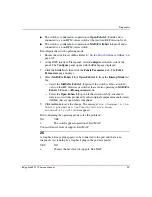
Is fault isolation being performed at the switch?
YES
NO
↓
Fault isolation is being performed at the EWS interface. Go to
step 12
.
4
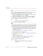
Ensure the switch reporting the problem is connected to facility AC power.
Inspect the switch for indications of being powered on, such as:
■
At the front bezel, an illuminated PWR LED (green) or ERR LED (amber).
■
Illuminated LEDs adjacent to Fibre Channel ports.
■
Audio emanations and airflow from cooling fans.
Does the switch appear powered on?
YES
NO
↓
An AC power distribution or CTP card failure is indicated. Go to
” on page 32. If this is the second time at this
step, replace the switch. Exit MAP.
5
Inspect cooling fans at the rear of the switch to ensure all fan blades are rotating.
Does cooling fan inspection indicate a failure (one or more cooling fans not
rotating)?
YES
NO
↓
Go to
step 7
.
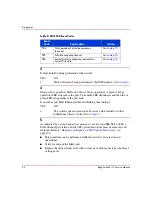
440
Embedded port hardware failed.
Go to
step 11
.
810
High temperature warning (CTP thermal
sensor).
Go to
step 10
.
811
Critically hot temperature warning (CTP
thermal sensor).
Go to
step 10
.
Table 7: MAP 400 Event Codes (Continued)
Event
Code
Explanation
Action


