background image

Diagnostics

41

Edge Switch 2/12 Service Manual

23

Inspect the switch for indications of being powered on, such as:

At the front bezel, an illuminated PWR LED (green) or ERR LED (amber).

Illuminated LEDs adjacent to Fibre Channel ports.

Audio emanations and airflow from cooling fans.

Does the switch appear powered on?

YES

NO

A power distribution problem is indicated. Go to 

step 18

 to obtain 

event codes. If no event codes are found, go to “

MAP 0100: Power 

Distribution Analysis

” on page 43. Exit MAP.

A faulty PWR LED is indicated, but switch and Fibre Channel port operation is 
not disrupted. The LED is connected to CTP card circuitry, and if this problem is 
a concern to the customer, the switch must be replaced. Exit MAP.

24

Is the amber ERR LED at the switch front bezel blinking?

YES

NO

Go to 

step 26

.

25

Unit beaconing is enabled for the switch.

1. Consult the customer and next level of support to determine the reason unit 

beaconing is enabled.

2. Disable unit beaconing at the EWS interface.

a.

At the View panel, select Operations at the left side of the panel. The 
Operations panel opens with the Switch and Beacon pages displayed.

b.

Click Deactivate to disable beaconing. The message 

Your changes 

have been successfully activated

 appears.

Was unit beaconing enabled because switch failure or degradation was suspected?

YES

NO

The switch appears operational. Exit MAP.

Go to 

step 19

 and perform fault isolation again (at the switch). If this is the second 

time at this step, contact the next level of support. Exit MAP.

Summary of Contents for StorageWorks Edge Switch 2/12

Page 1: ...2 Product Version FW v06 xx HAFM SW v08 02 00 Second Edition July 2004 Part Number AA RURDB TE This manual describes diagnostic repair and removal and replacement procedures for field replaceable units FRUs for the HP StorageWorks Edge Switch 2 12 ...

Page 2: ...ubject to change without notice The only warranties for HP products and services are set forth in the express warranty statements accompanying such products and services Nothing herein should be construed as constituting an additional warranty HP shall not be liable for technical or editorial errors or omissions contained herein Microsoft and Windows are U S registered trademarks of Microsoft Corp...

Page 3: ... storage web site 15 HP authorized reseller 15 1 General Information 17 Switch Description 17 Error Detection Reporting and Serviceability Features 19 Software Diagnostic Features 20 EWS Interface 20 SNMP Trap Message Support 22 Maintenance Approach 23 Tools and Test Equipment 24 Tools Supplied with the Switch 24 Tools Supplied by Service Personnel 25 Additional Information 26 2 Diagnostics 27 Mai...

Page 4: ...95 Port List Page 95 Port Stats Page 97 Port Properties Page 100 Perform Port Diagnostic Loopback Tests 101 Internal Loopback Test 102 External Loopback Test 103 Collect Maintenance Data 105 Set the Switch Online or Offline 107 Set Online State 107 Set Offline State 108 Block or Unblock a Port 109 Block a Port 109 Unblock a Port 110 Clean Fiber Optic Components 111 Power On Procedure 112 Power Off...

Page 5: ...h 599 162 Thermal Events 800 through 899 171 Index 173 Figures 1 Edge Switch 2 12 20 2 EWS interface View panel 22 3 Multi mode and single mode loopback plugs 26 4 Fiber optic protective plug 26 5 Null modem cable 27 6 View panel EWS interface 35 7 View panel Port Properties tab 38 8 View panel FRU Properties tab 40 9 Monitor panel Log page 41 10 Connection Description dialog box 53 11 Connect To ...

Page 6: ...ons panel Switch page with Reset Config tab 124 32 Browser specific message box 124 33 Front accessible FRUs 132 34 Miscellaneous parts 133 Tables 1 Document conventions 13 2 Factory Set Defaults 29 3 MAP Summary 30 4 Event Codes versus Maintenance Action 30 5 MAP 0200 Event Codes 49 6 MAP 0200 Byte 0 FRU Codes 49 7 MAP 400 Event Codes 56 8 MAP 500 Event Codes 61 9 Port Operational States and Acti...

Page 7: ...Code 081 194 35 Event Code 120 196 36 Event Code 121 196 37 Event Code 140 197 38 Event Code 141 197 39 Event Code 142 198 40 Event Code 143 198 41 Event Code 150 199 42 Event Code 151 201 43 Event Code 300 202 44 Event Code 301 202 45 Event Code 302 203 46 Event Code 310 203 47 Event Code 311 204 48 Event Code 312 204 49 Event Code 400 205 50 Event Code 410 205 51 Event Code 411 206 52 Event Code...

Page 8: ...Code 508 213 64 Event Code 510 214 65 Event Code 512 214 66 Event Code 513 215 67 Event Code 514 215 68 Event Code 523 216 69 Event Code 524 216 70 Event Code 525 217 71 Event Code 581 217 72 Event Code 582 218 73 Event Code 583 218 74 Event Code 584 219 75 Event Code 585 219 76 Event Code 586 220 77 Event Code 810 221 78 Event Code 811 221 ...

Page 9: ...s information to help you Monitor and troubleshoot the Edge Switch 2 12 Perform procedures to isolate and resolve problems Repair and maintain the switch Remove and replace field replaceable units FRUs About this Guide topics include Overview page 10 Conventions page 11 Rack stability page 14 Getting help page 15 ...

Page 10: ...nnel switches by Hewlett Packard Related documentation For a list of corresponding documentation included with this product see the Related Documents section of the HP StorageWorks Edge Switch Release Notes For the latest information documentation and firmware releases please visit the HP StorageWorks website http h18006 www1 hp com storage saninfrastructure html For information about Fibre Channe...

Page 11: ...ions in the warning could result in bodily harm or death Caution Text set off in this manner indicates that failure to follow directions could result in damage to equipment or data Table 1 Document conventions Convention Element Blue text Figure 1 Cross reference links Bold Menu items buttons and key tab and box names Italics Text emphasis and document titles in body text Monospace font User input...

Page 12: ...ence of electrical shock hazards Enclosed area contains no operator serviceable parts WARNING To reduce the risk of personal injury from electrical shock hazards do not open this enclosure Any RJ 45 receptacle marked with these symbols indicates a network interface connection WARNING To reduce the risk of electrical shock fire or damage to the equipment do not plug telephone or telecommunications ...

Page 13: ...shock remove all power cords to completely disconnect power from the power supplies and systems Any product or assembly marked with these symbols indicates that the component exceeds the recommended weight for one individual to handle safely WARNING To reduce the risk of personal injury or damage to the equipment observe local occupational health and safety requirements and guidelines for manually...

Page 14: ...ipment be sure that The leveling jacks are extended to the floor The full weight of the rack rests on the leveling jacks In single rack installations the stabilizing feet are attached to the rack In multiple rack installations the racks are coupled Only one rack component is extended at any time A rack may become unstable if more than one rack component is extended for any reason ...

Page 15: ...on available before calling Technical support registration number if applicable Product serial numbers Product model names and numbers Applicable error messages Operating system type and revision level Detailed specific questions HP storage web site The HP web site has the latest information on this product as well as the latest drivers Access storage at http www hp com country us eng prodserv sto...

Page 16: ...About this Guide 16 Edge Switch 2 12 Service Manual ...

Page 17: ...gnostic Features page 20 Maintenance Approach page 23 Tools and Test Equipment page 24 Additional Information page 26 Switch Description The Edge Switch 2 12 provides Fibre Channel device connectivity through 12 ports that operate at either 1 0625 or 2 125 gigabits per second Gbps and can be configured as Fabric ports F_Ports to provide direct connectivity for up to 12 switched fabric devices Fabr...

Page 18: ... configuration statistics monitoring and basic operation The EWS interface is opened from a standard Web browser running Netscape Navigator 4 6 or higher or Microsoft Internet Explorer 4 0 or higher At the browser enter the Internet Protocol IP address of the switch as the Internet uniform resource locator URL When prompted at a login screen enter a user name and password The Edge Switch 2 12 prov...

Page 19: ...ange the switch s IP address subnet mask and gateway address These parameters can also be changed through a Telnet session access for which is provided through a local or remote PC with an Ethernet connection to the switch Data collection through the EWS interface to help isolate system problems The data includes a memory dump file and audit hardware and engineering logs Beaconing to assist servic...

Page 20: ...tted to up to six authorized management workstations EWS Interface The EWS interface provides a GUI accessed through an Ethernet network locally or remotely to manage monitor and isolate problems for the Edge Switch 2 12 When the interface opens the default display is the View panel as shown in Figure 2 Figure 2 EWS interface View panel Task selection tabs appear at the top of the panel a graphica...

Page 21: ...figure panel the Ports default Switch Management Zoning Security and Performance task selection tabs appear Monitor At the Monitor panel the Port List default Port Stats Log and Node List task selection tabs appear Operations At the Operations panel the Switch default Port Maintenance and Feature Installation task selection tabs appear Help The Help selection opens online user documentation that s...

Page 22: ...lthough SNMP trap messages are typically transmitted to customer personnel only the messages may be provided to service personnel as initial notification of a switch problem or as information included in the fault isolation process Generic SNMP traps include coldStart reports that the SNMP agent is reinitializing due to a switch reset warmStart reports that the SNMP agent is reinitializing due to ...

Page 23: ...ssing the EWS interface Link failure between a port and attached device ISL failure or segmentation of an E_Port Fault isolation and service procedures vary depending on the system event information provided Fault isolation and related service information are provided through maintenance analysis procedures MAPs documented in Chapter 3 MAPs consist of step by step procedures that prompt service pe...

Page 24: ... type of port transceivers installed Both plugs are shipped if shortwave laser and longwave laser transceivers are installed The plug is shown in Figure 3 Figure 3 Multi mode and single mode loopback plugs Fiber optic protective plug For safety and port transceiver protection fiber optic protective plugs must be inserted in all port SFPs without fiber optic cables attached The switch is shipped wi...

Page 25: ...tandard flat tip and cross tip Phillips screwdrivers Screwdrivers are required to remove replace adjust or tighten various connector or chassis components Maintenance terminal desktop or notebook PC The PC is required to configure switch network addresses and acquire event log information through the maintenance port The PC must have The Microsoft Windows 98 Windows 2000 or Windows Millennium Edit...

Page 26: ...tch 2 12 front and rear panel features field replaceable units FRUs management options operational features optional kits installation configuration and technical specifications refer to the HP StorageWorks Edge Switch 2 12 Installation Guide For information on managing the Edge Switch 2 12 using the Embedded Web Server interface refer to the HP StorageWorks Embedded Web Server User Guide ...

Page 27: ...on and related service procedures MAPs consist of step by step procedures that prompt service personnel for information or describe a specific action to be performed MAPs provide information to interpret system events isolate a switch failure repair the failure and verify switch operation Factory Defaults Table 2 lists the defaults for the passwords and IP subnet and gateway addresses for the Edge...

Page 28: ...alysis page 59 MAP 0600 Fabric ISL and Segmented Port Problem Determination page 76 Table 4 Event Codes versus Maintenance Action Event Code Explanation Action 011 Login Server database invalid Go to MAP 0600 Fabric ISL and Segmented Port Problem Determination 021 Name Server database invalid Go to MAP 0600 Fabric ISL and Segmented Port Problem Determination 031 SNMP request received from unauthor...

Page 29: ...me delivery error threshold exceeded Go to Collect Maintenance Data on page 105 080 Unauthorized worldwide name Go to MAP 0500 Port Failure and Link Incident Analysis 081 Invalid attachment Go to MAP 0500 Port Failure and Link Incident Analysis 120 Error detected while processing system management command Go to Go to Collect Maintenance Data on page 105 121 Zone set activation failed zone set too ...

Page 30: ...er up diagnostic failure Go to MAP 0200 POST Failure Analysis 410 Switch reset No action required 411 Firmware fault Go to MAP 0200 POST Failure Analysis 412 CTP watchdog timer reset Go to Collect Maintenance Data on page 105 421 Firmware download complete No action required 423 CTP firmware download initiated No action required 426 Multiple ECC single bit errors occurred Go to MAP 0400 FRU Failur...

Page 31: ... required 525 FL_Port arbitration timeout No action required 581 Implicit incident Go to MAP 0500 Port Failure and Link Incident Analysis 582 Bit error threshold exceeded Go to MAP 0500 Port Failure and Link Incident Analysis 583 Loss of signal or loss of synchronization Go to MAP 0500 Port Failure and Link Incident Analysis 584 Not operational primitive sequence received Go to MAP 0500 Port Failu...

Page 32: ...er PC and all switches The internet protocol IP address gateway address and subnet mask for the switch reporting the problem The administrator user name and password of the customer supplied server accessing the EWS interface Both are case sensitive and required when prompted at the username and password entry dialog box Continue to the next step 2 Are you at a PC with a Web browser such as Netsca...

Page 33: ... At the Netsite field Netscape Navigator or Address field Internet Explorer type http xxx xxx xxx xxx where xxx xxx xxx xxx is the IP address of the switch obtained in step 1 A username and password entry dialog box appears 4 Type the user name and password obtained in step 1 and click OK The EWS interface opens with the View panel displayed Figure 6 Figure 6 View panel EWS interface Continue to t...

Page 34: ... the switch reporting the problem is connected to facility AC power Inspect the switch for indications of being powered on such as At the front bezel an illuminated PWR LED green or ERR LED amber Illuminated LEDs adjacent to Fibre Channel ports Audio emanations and airflow from cooling fans Does the switch appear powered on YES NO A power distribution problem is indicated Go to MAP 0100 Power Dist...

Page 35: ... box appears 3 Type the user name and password obtained in step 1 and click OK If the View panel does not display wait another five minutes and perform this step again Does the EWS interface appear operational with the View panel displayed YES NO Perform fault isolation at the switch Go to step 19 10 At the View panel and Switch page inspect the Status field at the top of the page Does the switch ...

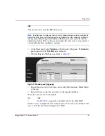
Page 36: ...Port Properties tab 2 Inspect the Beaconing and Operational State fields Does the Beaconing field display an On message YES NO Go to step 13 12 Port beaconing is enabled 1 Consult the customer and next level of support to determine the reason port beaconing is enabled ...

Page 37: ...ate field display a Segmented message NO YES Port segmentation is indicated Go to step 18 to obtain event codes If no event codes are found go to MAP 0600 Fabric ISL and Segmented Port Problem Determination on page 76 Exit MAP 14 At the View panel does the Operational State field display a message indicating a port problem NO YES Go to step 18 to obtain event codes If no event codes are found go t...

Page 38: ...ssage for the power supply NO YES A power supply failure is indicated Go to step 18 to obtain event codes If no event codes are found go to MAP 0100 Power Distribution Analysis on page 43 Exit MAP 17 Inspect the Status fields for switch FRUs Does the State field display a Failed message for any of the FRUs YES NO The switch appears operational Exit MAP A FRU failure is indicated Continue to the ne...

Page 39: ...mal indication after a problem is resolved 1 At the View panel select Monitor at the left side of the panel The Monitor panel opens with the Port List page displayed 2 Click the Log tab The Log page displays Figure 9 Figure 9 Monitor panel Log page 3 Record the event code date time and severity Informational Minor Major or Severe 4 Record all event codes that may relate to the reported problem Wer...

Page 40: ... LEDs adjacent to Fibre Channel ports Audio emanations and airflow from cooling fans Does the switch appear powered on YES NO A power distribution problem is indicated Go to step 18 to obtain event codes If no event codes are found go to MAP 0100 Power Distribution Analysis on page 43 Exit MAP 22 Is the green PWR LED at the switch front bezel illuminated NO YES Go to step 24 A faulty PWR LED is in...

Page 41: ...concern to the customer the switch must be replaced Exit MAP 24 Is the amber ERR LED at the switch front bezel blinking YES NO Go to step 26 25 Unit beaconing is enabled for the switch 1 Consult the customer and next level of support to determine the reason unit beaconing is enabled 2 Disable unit beaconing at the EWS interface a At the View panel select Operations at the left side of the panel Th...

Page 42: ...0 Port Failure and Link Incident Analysis on page 59 Exit MAP 28 The link incident record provides the attached switch port number s and one or more of the following event codes and messages Record all event codes that may relate to the reported problem 581 Link interface incident implicit incident 582 Link interface incident bit error threshold exceeded 583 Link failure loss of signal or loss of ...

Page 43: ...lity power receptacle If not connect the cord as directed by the customer 2 Ensure the associated facility circuit breaker is on If not ask the customer to set the circuit breaker on 3 Ensure the AC power cord is not damaged If damaged replace the cord Was a corrective action performed YES NO Go to step 4 3 Verify power supply and switch operation Inspect the switch for indications of being powere...

Page 44: ...such as At the front bezel an illuminated PWR LED green or ERR LED amber Illuminated LEDs adjacent to Fibre Channel ports Audio emanations and airflow from cooling fans Is a power supply or power distribution system failure indicated YES NO The switch appears operational Exit MAP 6 The power supply may be operational but the CTP card is not receiving DC power The in card circuit breaker may have t...

Page 45: ... connected to facility AC power Inspect the switch for indications of being powered on such as At the front bezel an illuminated PWR LED green or ERR LED amber Illuminated LEDs adjacent to Fibre Channel ports Audio emanations and airflow from cooling fans Is a power supply or power distribution system failure indicated YES NO Analysis for an Ethernet link or CTP card failure is not described in th...

Page 46: ...t to initialize the switch and bring it online An event code 400 displays when the switch completes the POST IML process 1 Ensure the switch reporting the problem is connected to facility AC power Inspect the switch for indications of being powered on such as At the front bezel an illuminated PWR LED green or ERR LED amber Illuminated LEDs adjacent to Fibre Channel ports Audio emanations and airfl...

Page 47: ... the failed FRU Byte 1 is the slot number of the failed FRU 00 for a nonredundant FRU Table 6 lists byte 0 FRU codes and suggested actions to isolate faults 5 The CTP card failed POSTs as indicated by FRU code 02 Replace the switch Exit MAP 6 A cooling fan failed POSTs as indicated by FRU code 05 Replace the switch Exit MAP Table 5 MAP 0200 Event Codes Event Code Explanation Action 400 Power up di...

Page 48: ...web browser PC running the EWS interface The failure indication is a Page cannot be found Unable to locate the server HTTP 404 file not found or other similar message Caution Prior to servicing a switch determine the Ethernet LAN configuration Installation of multiple switches on a public customer intranet can complicate problem determination and fault isolation 1 Does the EWS interface appear ope...

Page 49: ... being powered on such as At the front bezel an illuminated PWR LED green or ERR LED amber Illuminated LEDs adjacent to Fibre Channel ports Audio emanations and airflow from cooling fans Does the switch appear powered on YES NO A power distribution problem is indicated Go to MAP 0100 Power Distribution Analysis on page 43 Exit MAP 4 At the front of the switch inspect the amber ERR LED Is the LED i...

Page 50: ...to isolate the problem for that device Exit MAP If the problem is associated with an unrelated device notify the customer and have the system administrator correct the problem Did repair of an unrelated LAN attached device solve the problem NO YES The switch to EWS PC connection is restored and appears operational Exit MAP 7 The IP address defining the switch to the Ethernet LAN must be verified A...

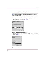
Page 51: ...ng the IP address using HyperTerminal serial communication software 5 At the Windows Workstation menu sequentially select Programs Accessories Communications and HyperTerminal The Connection Description dialog box displays Figure 10 Figure 10 Connection Description dialog box 6 Type Edge 12 in the Name field and click OK The Connect To dialog box displays Figure 11 Figure 11 Connect To dialog box ...

Page 52: ...econd 115200 Data bits 8 Parity None Stop bits 1 Flow control Hardware or None When the parameters are set click Apply and OK The Edge 12 HyperTerminal dialog box displays 9 At the prompt type the user level password default is password and press Enter The password is case sensitive The Edge 12 HyperTerminal dialog box displays with a C prompt at the bottom of the window 10 At the C prompt type ip...

Page 53: ...onfirmation message displays Figure 14 Figure 14 Disconnect message box 13 Click Yes A second HyperTerminal dialog box displays Figure 15 Figure 15 Save Session message box 14 Click No to exit and close the HyperTerminal application 15 Power off the maintenance terminal 16 Disconnect the RS 232 null modem cable from the switch and the maintenance terminal Replace the protective cap over the mainte...

Page 54: ...WS Event Log The amber LED on the FRU illuminates A Failed message associated with a FRU at the EWS interface 1 Was an event code 300 301 302 426 433 440 810 or 811 observed at the EWS Event Log YES NO Go to step 3 2 Table 7 lists event codes brief explanations of the codes and suggested actions to isolate faults Table 7 MAP 400 Event Codes Event Code Explanation Action 300 Cooling fan propeller f...

Page 55: ...om cooling fans Does the switch appear powered on YES NO An AC power distribution or CTP card failure is indicated Go to MAP 0000 Start MAP on page 32 If this is the second time at this step replace the switch Exit MAP 5 Inspect cooling fans at the rear of the switch to ensure all fan blades are rotating Does cooling fan inspection indicate a failure one or more cooling fans not rotating YES NO Go...

Page 56: ... select Operations at the left side of the panel The Operations panel opens with the Switch and Beacon pages displayed b Click Deactivate to disable beaconing The message Your changes have been successfully activated appears Was unit beaconing enabled because a failure or degradation was suspected NO YES Go to step 1 The switch appears operational Exit MAP 9 Is the green PWR LED illuminated the am...

Page 57: ...llect Maintenance Data on page 105 Exit MAP 11 An event code 433 or 440 indicates a CTP card failure Replace the switch Exit MAP 12 Does the EWS interface appear operational NO YES Go to step 14 13 A Page cannot be found Unable to locate the server HTTP 404 file not found or other similar message appears The message indicates the PC cannot communicate with the switch because The switch to PC Ether...

Page 58: ... or power supply failure is indicated Replace the switch Exit MAP 15 Inspect the CTP card operational state at the EWS interface 1 At the View panel click the FRU Properties tab The FRU Properties tab displays 2 Inspect the Status field for the CTP card Does the Status field display a Failed message for the CTP card NO YES A CTP card failure is indicated Replace the switch Exit MAP Additional anal...

Page 59: ...n event code 080 081 506 507 512 514 581 582 583 584 585 or 586 observed at the EWS Event Log NO YES Go to step 2 2 Table 8 lists event codes brief explanations of the codes and suggested actions to isolate faults Table 8 MAP 500 Event Codes Event Code Explanation Action 080 Unauthorized worldwide name Go to step 12 081 Invalid attachment Go to step 23 506 Fibre Channel port failure Go to step 23 ...

Page 60: ...ay have occurred Go to step 15 5 As indicated by a visual inspection message or event code 506 512 or 514 a Fibre Channel port failed and the SFP optical transceiver must be removed and replaced Refer to Remove and Replace an SFP Optical Transceiver on page 126 This procedure can be performed while the switch is powered on and operational Verify location of the failed port Replace the optical tran...

Page 61: ...e with the switch because The switch to PC Ethernet link could not be established AC power distribution in the switch failed or AC power was disconnected The switch CTP card failed Continue to the next step 8 Ensure the switch reporting the problem is connected to facility AC power Inspect the switch for indications of being powered on such as At the front bezel an illuminated PWR LED green or ERR...

Page 62: ...switch port is unblocked and receiving the offline sequence OLS or not operational sequence NOS from an attached device Inform the customer that the attached device failed or is set offline Ask the customer to take the appropriate corrective action Exit MAP Table 9 Port Operational States and Actions Operational State Action Online No action required Exit MAP Port Failure Go to step 9 Offline Go t...

Page 63: ... the EWS interface 1 At the View panel select Configure at the left side of the panel The Configure panel opens with the Ports page displayed 2 Click the Security tab then click the Port Binding tab The Port Binding page displays 3 Inspect entries in the Port WWN column These are WWNs assigned to the port or Fibre Channel interface installed on the attached device If a nickname is not assigned to ...

Page 64: ...ly activated appears 2 Perform an external loopback test for all ports that were reset Refer to Perform Port Diagnostic Loopback Tests on page 101 Did resetting ports solve the problem NO YES The switch appears operational Exit MAP 14 Port beaconing may be enabled 1 Consult the customer and next level of support to determine the reason port beaconing is enabled 2 Disable port beaconing at the EWS ...

Page 65: ...the link incident recurs Did a link incident recur YES NO The switch appears operational Exit MAP 16 A link incident has occurred and requires attention Go to step 17 17 Inspect the fiber optic jumper cable attached to the port and ensure the cable is not bent and connectors are not damaged If the cable is bent or connectors are damaged 1 Notify the customer the port will be blocked Ensure the cus...

Page 66: ... offline 2 Block the port Refer to Block or Unblock a Port on page 109 3 Disconnect both ends of the fiber optic cable 4 Clean the fiber optic connectors Refer to Clean Fiber Optic Components on page 111 5 Reconnect the fiber optic cable 6 Unblock the port Refer to Block or Unblock a Port on page 109 7 Monitor port operation for approximately five minutes Did a link incident or No Light message re...

Page 67: ...e problem is causing the recurrent link incident or No Light message The recurring problem indicates port degradation and a possible pending failure Go to step 21 23 As indicated by a message or event code 081 a port has an invalid attachment The information in the Port Properties dialog box specifies the reason as listed in Table 10 Table 10 Invalid Attachment Reasons and Actions Reason Action Un...

Page 68: ...L 3 Click Activate to save the change The message Your changes to the Port Configuration have been successfully activated appears Did reconfiguring the port type solve the problem NO YES The switch appears operational Exit MAP Contact the next level of support Exit MAP 25 One of the following mode mismatch conditions was detected and an ISL connection is not allowed The switch is configured for op...

Page 69: ...1 0 or Open Fabric 1 0 from the Interop Mode list box Select the McDATA Fabric 1 0 option if the switch is fabric attached only to other HP directors or switches that are also operating in McDATA Fabric 1 0 mode or Homogeneous mode Select the Open Fabric 1 0 option if the switch is fabric attached to directors or switches produced by other original equipment manufacturers OEMs that are open fabric...

Page 70: ...se of an unresponsive device node or an ISL connection was not allowed because of a security violation authorization failure reject Check the port status and clean the fiber optic connectors on the cable 1 Notify the customer the port will be blocked Ensure the customer s system administrator quiesces Fibre Channel frame traffic through the port and sets the attached device offline 2 Block the por...

Page 71: ...tches 4 Ensure the Connection Policy Enable Restrict E_Ports Enable Restrict F_Ports Enable Restrict All Ports or Disable Switch Binding is compatible for both switches 5 The Attached Nodes drop down list contains the world wide names of attached Fibre Channel devices Ensure these switch binding membership lists are compatible for both switches To add a member node or device to the switch binding ...

Page 72: ...ring the fabric and switch binding parameters solve the problem NO YES The switch appears operational Exit MAP Contact the next level of support Exit MAP 31 A port connection is not allowed because of a fabric binding mismatch between fabric elements Fabric binding membership lists must be compatible for both switches At the EWS interface for both switches 1 At the View panel select Configure at t...

Page 73: ... tab The Switch Binding page displays 3 The Attached Nodes drop down list contains the world wide names of attached Fibre Channel devices Ensure these switch binding membership lists are compatible for both switches To add a member node or device to the switch binding membership list displayed at the bottom of the page select a WWN from the Attached Nodes drop down list and click the adjacent Add ...

Page 74: ...er and resume operation NO YES The Fibre Channel link and switch appear operational Exit MAP Go to step 1 35 A switch port state is inactive because the Flexport Technology feature key is not installed for the port Fibre Channel ports 4 through 11 only or because of a transmission speed conflict between the port configuration and the SFP optical transceiver Is the inactive port a Base configuratio...

Page 75: ...nt to the list box for the port and select a port speed as follows Select 1 Gb sec if a one gigabit per second Gbps optical transceiver is installed in the port Select 2 Gb sec if a two Gbps optical transceiver is installed in the port 3 Click Activate to save the change The message Your changes to the Port Configuration have been successfully activated appears Did reconfiguring the port speed sol...

Page 76: ... to step 17 MAP 0600 Fabric ISL and Segmented Port Problem Determination This MAP describes fault isolation of fabric logout interswitch link ISL and E_Port segmentation problems Failure indicators include An event code recorded at the EWS Event Log A segmentation reason associated with a Fibre Channel port at the EWS interface 1 Base product Fibre Channel ports on the Edge Switch 2 12 can be conf...

Page 77: ...140 142 or 150 observed at the EWS Event Log YES NO Go to step 5 4 Table 11 lists event codes brief explanations of the codes and suggested actions to isolate faults Table 11 MAP 600 Event Codes Event Code Explanation Action 011 Login Server database invalid Go to step 7 021 Name Server database invalid Go to step 7 051 Management Server database invalid Go to step 8 052 Management Server internal...

Page 78: ...ayed 2 Click the port number 0 through 11 of the segmented port 3 Inspect the Reason field for the selected port Is the Reason field blank or does it display an N A message NO YES The switch ISL appears operational Exit MAP The Reason field displays a segmentation reason message Table 12 lists the reasons and suggested actions to isolate faults 140 Congestion detected on an ISL Go to step 21 142 L...

Page 79: ...d devices The following list explains the error Event code 051 The Management Server database failed CRC validation Event code 052 An internal operating error was detected by the Management Server subsystem All attached devices resume operation after Management Server login Perform the procedure described in Collect Maintenance Data on page 105 Exit MAP 9 As indicated by an event code 061 a minor ...

Page 80: ... Director 2 64 in a multiswitch fabric that has more than the proscribed number of ISLs Director 2 140 in a multiswitch fabric that has more than the proscribed number of ISLs Other fabric element director or switch in a multiswitch fabric that has more than the proscribed number of ISLs Fibre Channel frames may be lost or routed in loops because of potential fabric routing problems Advise the cus...

Page 81: ...t or engineering personnel to determine the recommended E_D_TOV and R_A_TOV values for both switches 2 Notify the customer both switches will be set offline Ensure the system administrator quiesces Fibre Channel frame traffic through the switches and sets attached devices offline 3 Set both switches offline Refer to Set the Switch Online or Offline on page 107 4 At the View panel select Configure ...

Page 82: ...ments had duplicate domain IDs 1 Work with the system administrator to determine the desired domain ID 1 through 31 inclusive for each switch 2 Notify the customer both switches will be set offline Ensure the system administrator quiesces Fibre Channel frame traffic through the switches and sets attached devices offline 3 Set both switches offline Refer to Set the Switch Online or Offline on page ...

Page 83: ...ame must be 64 characters or fewer in length The first character must be a letter a through z upper or lower case Other characters must be alphanumeric a through z or 0 through 9 dollar sign hyphen caret or underscore _ 2 At the View panel select Configure at the left side of the panel The Configure panel opens with the Ports page displayed 3 Click the Zoning tab then click the Zones tab The Zones...

Page 84: ... IML solve the problem and did both switches join through the ISL to form a fabric NO YES The switch associated ISL and multiswitch fabric appear operational Exit MAP Perform the data collection procedure and contact the next level of support Exit MAP 18 A switch E_Port segmented because no switch in the fabric is capable of becoming the principal switch 1 Notify the customer the switch will be se...

Page 85: ...nd the message No Principal Switch appears in the Reason field of the Port Properties page 5 At the Switch Priority field select Principal Never Principal or Default the default setting is Default then click Activate to save the change The message Your changes to the Fabric Parameters configuration have been successfully activated appears 6 Set the switch online Refer to Set the Switch Online or O...

Page 86: ...e ISL link speed between the switches reporting the problem from 1 Gbps to 2 Gbps Reroute Fibre Channel traffic by moving device connections to a less congested region of the fabric Did the corrective action solve the problem and relieve the reported ISL congestion NO YES The ISL appears operational Exit MAP Contact the next level of support Exit MAP 22 A 142 event code occurs only if the optional...

Page 87: ...of a zone merge frame This event code always precedes a 070 event code and represents the reply of an adjacent fabric element in response to a zone merge frame Obtain supplementary event data for each 150 event code 1 At the EWS Event Log examine the first 12 bytes 0 through 11 of event data 2 Bytes 0 through 3 specify the E_Port number 00 through 11 reporting the problem Bytes 8 through 11 specif...

Page 88: ...necting and reconnecting the cable solve the problem and was the resulting zone merge process successful NO YES The merged zone appears operational Exit MAP Perform the procedure described in Collect Maintenance Data on page 105 Contact the next level of support Exit MAP 25 A zone merge process failed during ISL initialization The following list explains the reason Failure reason 09 Invalid data c...

Page 89: ...ing Log Information page 91 Obtain Port Diagnostic Information page 92 Collect Maintenance Data page 105 Set the Switch Online or Offline page 107 Block or Unblock a Port page 109 Clean Fiber Optic Components page 111 Power On Procedure page 112 Power Off Procedure page 113 IML or Reset the Switch page 114 Manage Firmware Versions page 116 Reset Configuration Data page 121 Do not perform repairs u...

Page 90: ...dure carefully and thoroughly to familiarize yourself with the information and reduce the possibility of problems or customer down time 2 When performing procedures described in this chapter heed all WARNING and CAUTION statements and other statements listed in the preface of this manual 3 After completing steps of a detailed procedure that is referenced from another procedure return to the initia...

Page 91: ...vent occurred Error Event Code Three digit code that describes the event Event codes are listed and described in Event Codes on page 133 Severity Severity of the event Informational Minor Major or Severe Event Data Up to 32 bytes of supplementary information if available in hexadecimal format Event data is described in Event Codes on page 133 You can manage log contents using the following buttons...

Page 92: ... as described in Table 15 Table 15 Port Operational States Port State Blue Green LED Amber LED Description Inactive On Off The port is inactive The reason appears in the Reason field at the Port Properties page of the EWS View panel Not Installed Off Off An optical transceiver is not installed in the switch port Not Operational Off Off The port is receiving the not operational sequence NOS from an...

Page 93: ...On or Blinking Blinking The port is beaconing The amber port LED blinks once every two seconds to enable users to locate the port Invalid Attachment On Off The port has an invalid attachment The reason appears in the Reason field of the Port Properties page of the EWS View panel Link Incident Off Off A link incident occurred The alert information appears in the EWS event log Link Reset Off Off The...

Page 94: ...connected switches from joining and forming a multiswitch fabric The reason appears in the Reason field of the Port Properties page of the EWS View panel Testing Off On Blinking Blinking The port is performing an internal loopback test The port is performing an external loopback test Table 15 Port Operational States Continued Port State Blue Green LED Amber LED Description ...

Page 95: ...ew panel appears as the default panel At the View panel select the Monitor option at the left side of the panel The Monitor panel opens with the Port List page displayed Figure 17 Figure 17 Monitor panel Port List page A row of information for each port 0 through 11 inclusive appears Each row consists of the following columns Port Switch port number Name Port name of 24 alphanumeric characters or ...

Page 96: ... E_Port or Testing Type Configured port type Settings are Fabric port F_Port Fabric mixed port FX_Port This setting also configures a port as a fabric loop port FL_Port Generic port G_Port This selection is available only if enabled through optional E_Port or Full Fabric feature key Generic mixed port GX_Port This setting also configures a port as a generic loop port GL_Port This selection is avai...

Page 97: ...ort List page displayed Click the Port Stats tab The Monitor panel displays with the Port Stats page selected Figure 18 Figure 18 Monitor panel Port Stats page The Port Stats page displays traffic and error statistics for one port Values update only when the page opens for a selected port or the user selects Get Port Statistics The page defaults to port 0 Increment or decrement the port number dis...

Page 98: ...or port failure Sync losses Synchronization losses are detected because an attached device was reset or disconnected from the port Signal losses Signal losses are detected because an attached device was reset or disconnected from the port Primitive sequence errors Incorrect primitive sequences are received from an attached device indicating Fibre Channel link level protocol violations Discarded fr...

Page 99: ...stination device is unavailable Frames too short Received frames were less than the Fibre Channel minimum size indicating the frame arrived at the switch port corrupted Frame corruption may be caused by device disconnection an optical transceiver failure at the device a bad fiber optic cable or a poor cable connection Class 2 statistics These entries provide information about Class 2 traffic inclu...

Page 100: ...l Port Properties page The Port Properties page displays information for one port Values update only when the page opens for a selected port or the user selects Get Port Properties The page defaults to port 0 Increment or decrement the port number displayed 0 through 11 inclusive by clicking Fwd or Back The page provides the following information Port Number Switch port number Port Name User defin...

Page 101: ...c to the installed optical transceiver including connector type transceiver optics data transmission distance optical media cable type and transmission speed Perform Port Diagnostic Loopback Tests Port diagnostics consist of internal and external loopback tests The tests are performed on any selected port at the EWS interface The tests are described as follows Internal loopback test An internal lo...

Page 102: ... in the port during the test A device can remain connected during the test 2 When the EWS interface opens the View panel and Switch page appear as the default At the View panel select the Operations option at the left side of the panel The Operations panel opens with the Switch page displayed 3 Click the Port and Diagnostics tabs The Port page displays with the Diagnostics tab selected Figure 20 F...

Page 103: ...on is enabled c Click Activate at the bottom of the page The port resets and the message Your changes have been successfully activated appears 9 Notify the customer the test is complete and the attached device can be set online External Loopback Test To perform an external loopback at the EWS interface 1 Notify the customer that a disruptive external loopback test is to be performed and the attach...

Page 104: ...o abort the loopback test 9 When the test completes results appear as Passed or Failed in the message area of the dialog box 10 Remove the loopback plug and reconnect the fiber optic jumper cable from the device to the port disconnected in step 2 11 Reset the tested port a Click the Reset tab The Port page displays with the Reset tab selected b For the tested port click enable the check box in the...

Page 105: ...viewable only by support personnel Note An optional full volatility feature is often required at military sites that process classified data If the feature is enabled through the switch s maintenance port a memory dump file that possibly includes classified Fibre Channel frames is not included as part of the data collection procedure To collect maintenance data retrieve the dump file from the CTP ...

Page 106: ...elect the floppy drive A from the Save in drop down menu type a descriptive name for the dump file in the File name field and click Save 7 A Download dialog box displays showing the estimated time remaining to complete the download process When the process finishes the dialog box changes to a Download complete dialog box 8 Click Close to close the dialog box 9 Remove the diskette with the newly co...

Page 107: ...to the switch Note When the switch is set offline the operation of attached Fibre Channel devices is disrupted Do not set the switch offline unless directed to do so by a procedural step or the next level of support Set Online State To set the switch online from the EWS interface 1 When the EWS interface opens the View panel and Switch page appear as the default At the View panel select the Operat...

Page 108: ...ch page appear as the default At the View panel select the Operations option at the left side of the panel The Operations panel opens with the Switch page displayed 2 Click the Online State tab The Switch page displays with the Online State tab selected Figure 23 3 Click Set Offline The switch goes offline and the message Your changes have been successfully activated appears ...

Page 109: ...rface opens the View panel and Switch page appear as the default At the View panel select the Configure option at the left side of the panel The Configure panel opens with the Ports page displayed Figure 24 Figure 24 Configure panel Ports page 2 Click the check box for the selected port in the Blocked column to block the port default is unblocked A check mark indicates the port is blocked 3 Click ...

Page 110: ...option at the left side of the panel The Configure panel opens with the Ports page displayed Figure 24 2 Click the check box for the selected port in the Blocked column to remove the check mark and unblock the port A blank box indicates the port is unblocked 3 Click Activate at the bottom of the page to save and activate the unblocked configuration The message Your changes to the Port Configuratio...

Page 111: ...tor as shown in part A of Figure 25 a Keep the air nozzle approximately 50 millimeters two inches from the end of the connector and hold the can upright b Blow compressed air on the surfaces and end of the connector continuously for approximately five seconds Figure 25 Clean fiber optic components 3 Gently wipe the end face and other surfaces of the connector with an alcohol pad as shown in part B...

Page 112: ...rd into a facility power source and power supply AC connector at the rear of the switch When the power cord is connected the switch powers on and performs power on self tests POSTs 3 During POSTs The green power PWR LED on the switch front panel illuminates The amber system error ERR LED on the switch front panel blinks momentarily while the switch is tested The green LED associated with the Ether...

Page 113: ... be powered off Ensure the customer s system administrator quiesces Fibre Channel frame traffic through the switch and sets attached FC AL devices offline 2 Set the switch offline For instructions refer to Set the Switch Online or Offline on page 107 3 Disconnect the power cord from the power supply AC connector at the rear of the switch ...

Page 114: ...l logic for the CTP card and reloads the firmware from FLASH memory Ethernet LAN interface causing the connection to the Web browser PC to drop momentarily until the connection automatically recovers Ports causing all Fibre Channel connections to drop momentarily until the connections automatically recover This causes attached devices to log out and log back in therefore data frames lost during sw...

Page 115: ...g and all front panel LEDs illuminate 2 Release the button to reset the switch During the reset The green power PWR LED on the switch front panel illuminates The amber system error ERR LED on the switch front panel blinks momentarily while the switch is tested The green LED associated with the Ethernet port blinks momentarily while the port is tested The blue green and amber LEDs associated with t...

Page 116: ...EWS interface Determine the firmware version actively running on the switch Add a firmware versions to the browser PC hard drive Download a firmware version to the switch Determine Switch Firmware Version To determine a switch firmware version from the EWS interface 1 When the EWS interface opens the View panel and Switch page appear as the default At the View panel click the Unit Properties tab T...

Page 117: ...rowser PC hard drive PC running the EWS interface 1 Obtain the new firmware version from the HP website Note The following path is subject to change a At the browser PC with Internet access open the HP website The uniform resource locator URL is http hp com country us eng support html b Follow links to the Edge Switch 2 12 firmware c Click the Edge Switch 2 12 Firmware Version XX YY ZZ entry where...

Page 118: ...hat accompany the firmware version This information supplements information provided in this general procedure 1 When the EWS interface opens the View panel and Switch page appear as the default At the View panel select the Operations option at the left side of the panel The Operations panel opens with the Switch page displayed 2 Click the Maintenance and Firmware Upgrade tabs The Maintenance page...

Page 119: ... 28 Figure 28 Browser specific message box 5 Click OK to download the firmware version to the switch The download process takes several minutes to complete during which the browser is unavailable 6 When the firmware version is downloaded to the switch and verified the following message box displays Figure 29 Figure 29 Firmware Received message box 7 After firmware verification the switch performs ...

Page 120: ...te message box 9 Click here to login to the switch and start a new EWS session A username and password entry dialog box displays 10 Type the user name and password Note The default user name is Administrator and the default password is password The user name and password are case sensitive 11 Click OK The EWS interface opens with the View panel open and the Switch page displayed ...

Page 121: ...om the EWS interface Note When switch configuration data is reset to factory default values all optional features are disabled 1 Notify the customer the switch is to be set offline Ensure the customer s system administrator quiesces Fibre Channel frame traffic through the switch and sets attached FC AL devices offline 2 Set the switch offline For instructions refer to Set the Switch Online or Offl...

Page 122: ...sage Your changes have been successfully activated appears 7 The switch IP address resets to the default address of 10 1 1 10 If the configured IP address prior to reset was the same as the default address the browser to switch Ethernet connection is not affected and the procedure is complete If the configured IP address prior to reset was not the same as the default address the browser to switch ...

Page 123: ...0 1 1 10 a At the browser enter the default IP address of 10 1 1 10 as the Internet uniform resource locator URL A username and password entry dialog box displays b Type the default user name and password Note The default user name is Administrator and the default password is password The user name and password are case sensitive c Click OK The EWS interface opens with the View panel open and the ...

Page 124: ...Repair Information 124 Edge Switch 2 12 Service Manual ...

Page 125: ...age 32 This chapter describes Procedural Notes page 125 Remove and Replace an SFP Optical Transceiver page 126 Procedural Notes Note the following 1 Read the removal and replacement procedures for the FRU before removing the FRU 2 Follow all WARNING and CAUTION statements and statements in the preface of this manual 3 After completing a FRU replacement clear the event code reporting the failure an...

Page 126: ...t Removal To remove an SFP optical transceiver 1 Notify the customer that the port with the defective transceiver will be blocked Ensure the customer s system administrator sets the attached device offline 2 Identify the defective port transceiver from The illuminated amber LED adjacent to the port At the EWS interface failure information associated with the port at the Port Properties page of the...

Page 127: ...echanism by rotating the wire locking bale up or down 90 degrees 3 Perform an external loopback test on the port Refer to Perform Port Diagnostic Loopback Tests on page 101 for instructions If the test fails go to MAP 0000 Start MAP on page 32 to isolate the problem 4 Reconnect the fiber optic jumper cable a Remove the protective cap from the cable connector and the protective plug from the port s...

Page 128: ...t and port technology information is correct c If a problem is indicated go to MAP 0000 Start MAP on page 32 MAP 0000 Start MAP on page 32 to isolate the problem 8 Restore communication to the port with the replacement transceiver as directed by the customer Refer to Block or Unblock a Port on page 109 for instructions Inform the customer the port is available 9 To clear the system error ERR LED o...

Page 129: ... Edge Switch 2 12 field replaceable units FRUs Exploded view illustrations are provided for Front accessible FRUs Miscellaneous parts Exploded view illustrations portray the switch disassembly sequence Illustrated FRUs are numerically keyed to associated tabular parts lists The parts lists also include part numbers descriptions and quantities ...

Page 130: ...bers to the figure part numbers descriptions and quantities Figure 33 Front accessible FRUs Table 16 Front Accessible FRU Parts List Ref Part Number Description Qty N A 348406 B21 Base assembly Edge Switch 2 12 without optics N A 1 300834 B21 Transceiver optical SFP shortwave laser LC connector 300m 2 125 Gbps 0 to 12 1 300835 B21 Transceiver optical SFP longwave laser LC connector 10 km 2 125 Gbp...

Page 131: ...reference number part number description and quantity Figure 34 Miscellaneous parts 1 3 2 Table 17 Miscellaneous Parts Ref Part Number Description Qty 1 254145 001 Plug loopback LC connector multimode 50 125 micron 1148 1 1 254146 001 Plug loopback LC connector singlemode 9 125 micron 1149 1 2 254144 001 Cable null modem DB9F DB9F connector 1 3 254143 001 Cable Ethernet 10 foot 1 ...

Page 132: ...Illustrated Parts Breakdown 132 Edge Switch 2 12 Service Manual ...

Page 133: ...ative An event usually indicates a switch operational state transition but may also indicate an impending state change threshold violation An event may also provide information only and not indicate an operational state change Event codes are grouped as follows 000 through 199 system events 300 through 399 fan events 400 through 499 CTP card events 500 through 599 port module events 800 through 89...

Page 134: ...l that indicates how critical an event is as follows 0 informational 2 minor 3 major 4 severe not operational Explanation a complete explanation of what caused the event Action the recommended course of action if any to resolve the problem Event Data supplementary event data if any that displays in the event log in hexadecimal format Distribution check marks in associated fields indicate where the...

Page 135: ...plementary data included with this event Distribution Switch HAFM Appliance Host EWS Event Log System Error LED Event Log E Mail Call Home Sense Info Link Incident Table 19 Event Code 021 Message Name Server database invalid Severity Minor Explanation Following an IML or firmware download the Name Server database failed its CRC validation All Fabric Services databases are initialized to an empty s...

Page 136: ...ibution Switch HAFM Appliance Host EWS Event Log System Error LED Event Log E Mail Call Home Sense Info Link Incident Table 21 Event Code 051 Message Management Server database invalid Severity Minor Explanation Following an IML or firmware download the Management Server database failed its CRC validation All Management Services databases are initialized to an empty state resulting in an implicit ...

Page 137: ... on page 105 Asynchronous status report activation No action required Mode register update No action required Event Data Supplementary data consists of reporting tasks of type eMST_SB2 with component_id eMSCID_SB2_CHPGM For each type of error or indication the subcomponent_id is Management Server internal error subcomponent_id is eMS_ELR_SB2_DEVICE_PROTOCOL_ERROR or eMS_ELR_SB2_MSG_PROCESSING_ERRO...

Page 138: ...24 Event Code 062 Message Maximum interswitch hop count exceeded Severity Informational Explanation The fabric controller software detected that a path to another fabric element Director or Edge Switch traverses more than seven interswitch links ISLs or hops This may result in Fibre Channel frames persisting in the fabric longer than standard timeout values allow Action If possible reconfigure the...

Page 139: ...ment Director or Edge Switch with too many ISLs Distribution Switch HAFM Appliance Host EWS Event Log System Error LED Event Log E Mail Call Home Sense Info Link Incident Table 26 Event Code 070 Message E_Port is segmented Severity Informational Explanation A switch E_Port recognized an incompatibility with an attached fabric element Director or Edge Switch preventing the switch from participating...

Page 140: ...r ensure zones with the same name contain identical zone members 4 Build fabric protocol error A protocol error was detected during incorporation of the switch into the fabric Disconnect the E_Port link reconnect the link and initial program load IPL the switch If the condition persists perform the procedure described in Collect Maintenance Data on page 105 5 No principal switch No Director or Edg...

Page 141: ...ations The same name is applied to a zone for the switch and another fabric element Director or Edge Switch but the zones contain different zone members Modify the zone name to make it unique or ensure zones with the same name contain identical zone members Event Data continued 4 Build fabric protocol error A protocol error was detected during incorporation of the switch into the fabric Disconnect...

Page 142: ... E Mail Call Home Sense Info Link Incident Table 29 Event Code 073 Message Fabric initialization error Severity Informational Explanation An error was detected during the fabric initialization sequence most likely caused by frame delivery errors Event data is intended for engineering evaluation Action Perform the procedure described in Collect Maintenance Data on page 105 Event Data Byte 0 error r...

Page 143: ... Bytes 4 8 Count of frame delivery timeouts Bytes 9 11 Count of frame delivery aborts Distribution Switch HAFM Appliance Host EWS Event Log System Error LED Event Log E Mail Call Home Sense Info Link Incident Table 31 Event Code 080 Message Unauthorized world wide name Severity Informational Explanation The world wide name of the device or switch plugged in the indicated port is not authorized for...

Page 144: ...itch operating mode to that mode Otherwise set the switch operating mode to Open Fabric 1 0 if connected to M Series Fabric Directors or Edge Switches in Open Fabric 1 0 mode or an Open Fabric compliant product manufactured by a different vendor 4 Incompatible switch The switch returned a Process ELP Reject Invalid Revision Level reason code because the attached fabric element is not compatible If...

Page 145: ...n invalid attachment state Check the port status of the attached fabric element and clean the link s fiber optic components cable and connectors If the problem persists contact support personnel to report the problem F Unauthorized switch binding WWN Switch binding is enabled and an attached device or fabric element has an incompatible switch membership list At the Switch Binding Membership List d...

Page 146: ...entary data included with the event Distribution Switch HAFM Appliance Host EWS Event Log System Error LED Event Log E Mail Call Home Sense Info Link Incident Table 34 Event Code 121 Message Zone set activation failed zone set too large Severity Informational Explanation This event occurs when the switch receives a zone set activation command that exceeds the size supported by the switch The switc...

Page 147: ...d region of the fabric Event Data Byte 0 Port number reporting congestion Distribution Switch HAFM Appliance Host EWS Event Log System Error LED Event Log E Mail Call Home Sense Info Link Incident Table 36 Event Code 141 Message Congestion relieved on an ISL Severity Informational Explanation Open Trunking firmware detected an ISL with Fibre Channel traffic that previously exceeded the configured ...

Page 148: ...r moving device connections to a less congested region of the fabric Event Data Byte 0 Port number reporting low BB_Credit Distribution Switch HAFM Appliance Host EWS Event Log System Error LED Event Log E Mail Call Home Sense Info Link Incident Table 38 Event Code 143 Message Low BB_Credit relieved on an ISL Severity Informational Explanation Open Trunking firmware detected an ISL with no transmi...

Page 149: ...then reconnect the link If the condition persists perform the procedure described in Collect Maintenance Data on page 105 09 Invalid data Invalid data caused a zone merge failure Inspect bytes 12 15 of the event data for error codes Refer to error code definitions listed on the following page to correct the problem 0A Cannot merge A Cannot Merge condition caused a zone merge failure Inspect bytes ...

Page 150: ...A 0A Invalid protocol 0B Invalid number of zone members 0C Invalid flags 0D Invalid zone member information length 0E Invalid zone member information format 0F Invalid zone member information port 10 Invalid zone set name length 11 Invalid zone name length 37 Invalid zone name 39 Duplicate zone 3C Invalid number of zone members 3D Invalid zone member type 3E Invalid zone set name 45 Duplicate memb...

Page 151: ...tation of the FC SW2 protocol and are typically complicated Decoding the event data requires engineering support Event data are as follows Bytes 0 3 Managing switch domain ID in internal format 1 31 Bytes 4 7 Fabric configuration operation that failed Bytes 8 11 Fabric configuration step that failed Bytes 12 15 Managed switch domain ID in internal format 1 31 Bytes 16 19 Response command code rece...

Page 152: ...inclusive Distribution Switch HAFM Appliance Host EWS Event Log System Error LED Event Log E Mail Call Home Sense Info Link Incident Table 42 Event Code 301 Message Cooling fan propeller failed Severity Major Explanation Two cooling fans out of three failed or are rotating at insufficient angular velocity The remaining fans are operational The amber LED illuminates at the rear of the power supply ...

Page 153: ... byte of event data byte 0 specifies the failed fan numbers 0 through 2 inclusive Distribution Switch HAFM Appliance Host EWS Event Log System Error LED Event Log E Mail Call Home Sense Info Link Incident Table 44 Event Code 310 Message Cooling fan propeller recovered Severity Informational Explanation One cooling fan out of three recovered All fans are operational Action No action required Event ...

Page 154: ...stribution Switch HAFM Appliance Host EWS Event Log System Error Indicator Event Log E Mail Call Home Sense Info Link Incident Table 46 Event Code 312 Message Cooling fan propeller recovered Severity Informational Explanation Three cooling fans out of three recovered All fans are operational Action No action required Event Data The first byte of event data byte 0 specifies the recovered fan number...

Page 155: ...ollows 02 CTP card 05 cooling fan 06 power supply assembly Byte 1 FRU slot number Distribution Switch HAFM Appliance Host EWS Event Log System Error LED Event Log E Mail Call Home Sense Info Link Incident Table 48 Event Code 410 Message Switch reset Severity Informational Explanation The switch reset due to system power up IML or manual reset A software reset can occur automatically after a firmwa...

Page 156: ...ed in Collect Maintenance Data on page 105 Event Data Bytes 0 through 3 fault identifier least significant byte first Distribution Switch HAFM Appliance Host EWS Event Log System Error LED Event Log E Mail Call Home Sense Info Link Incident Table 50 Event Code 412 Message CTP watchdog timer reset Severity Informational Explanation The hardware watchdog timer expired and caused the CTP card to rese...

Page 157: ...yte 2 always a period Bytes 3 and 4 maintenance level yy Byte 5 always a period Bytes 6 and 7 interim release level zz Byte 8 always a space Bytes 9 through 12 build ID bbbb Distribution Switch HAFM Appliance Host EWS Event Log System Error LED Event Log E Mail Call Home Sense Info Link Incident Table 52 Event Code 423 Message CTP firmware download initiated Severity Informational Explanation The ...

Page 158: ...error interrupts Distribution Switch HAFM Appliance Host EWS Event Log System Error LED Event Log E Mail Call Home Sense Info Link Incident Table 54 Event Code 433 Message Non recoverable Ethernet fault Severity Major Explanation A non recoverable Ethernet interface failure was detected and the LAN connection to the Ethernet network was terminated No failure information or event codes are reported...

Page 159: ... Informational Explanation The switch detected a deviation in the normal operating mode or status of the embedded port Action No action required An additional event code is generated if this incident exceeds an error threshold or results in a port failure Event Data Byte 0 port number Byte 1 engineering reason code Bytes 4 through 7 elapsed millisecond tick count Bytes 8 and 9 high availability er...

Page 160: ...is incident exceeds an error threshold that results in a system event Event Data Byte 0 port number Byte 1 engineering reason code Bytes 4 through 7 elapsed millisecond tick count Bytes 8 and 9 high availability error callout 1 Bytes 10 and 11 high availability error callout 2 Byte 12 detecting port Byte 13 connected port Bytes 16 and 17 high availability error callout 3 Bytes 18 and 19 high avail...

Page 161: ...orms an IPL when the feature key is enabled Event data indicates which feature or features are installed Action No action required Event Data Byte 0 feature description as follows 00 through 04 Flexport 06 open system management server Byte 1 feature description as follows 06 SANtegrity Binding 07 Open Trunking Distribution Switch HAFM Appliance Host EWS Event Log System Error LED Event Log E Mail...

Page 162: ...n Collect Maintenance Data on page 105 Perform a switch reset If the problem persists replace the switch Event Data Byte 0 port number 00 through 11 Byte 1 engineering reason code Bytes 4 through 7 elapsed millisecond tick count Bytes 8 through 11 reason code specific Byte 16 connector type Bytes 17 and 18 transmitter technology Byte 19 distance capabilities Byte 20 supported transmission media By...

Page 163: ...Event Log System Error LED Event Log E Mail Call Home Sense Info Link Incident Table 61 Event Code 508 Message Fibre Channel port anomaly detected Severity Informational Explanation The switch detected a deviation in the normal operating mode or status of the indicated Fibre Channel port Action No action required An event code 506 is generated if this anomaly results in a hard port failure Event D...

Page 164: ...tion No action required Event Data Byte 0 port number 00 through 11 Bytes 4 through 7 elapsed millisecond tick count Distribution Switch HAFM Appliance Host EWS Event Log System Error LED Event Log E Mail Call Home Sense Info Link Incident Table 63 Event Code 512 Message SFP optical transceiver nonfatal error Severity Minor Explanation Switch firmware detected an SFP optical transceiver non fatal ...

Page 165: ...nt Log E Mail Call Home Sense Info Link Incident Table 65 Event Code 514 Message SFP optical transceiver failure Severity Major Explanation An SFP optical transceiver failed The amber LED corresponding to the port illuminates to indicate the failure Other ports remain operational if their LEDs are extinguished Action Replace the failed transceiver with a functional transceiver of the same type Eve...

Page 166: ...e OPN sequence Distribution Switch HAFM Appliance Host EWS Event Log System Error LED Event Log E Mail Call Home Sense Info Link Incident Table 67 Event Code 524 Message No AL_PA acquired Severity Informational Explanation Switch cannot allocate an AL_PA of 0 loop master for an FC AL device during loop initialization The device cannot participate in loop operation Action Disconnect the FC AL devic...

Page 167: ...ense Info Link Incident Table 69 Event Code 581 Message Implicit incident Severity Major Explanation The event caused an implicit Fibre Channel link incident Action A link incident record LIR is generated and sent to the attached server using the reporting procedure defined in T11 99 017v0 OSI If fault isolation at the server does not detect a failure the problem may be due to a port failure Go to...

Page 168: ...t EWS Event Log System Error LED Event Log E Mail Call Home Sense Info Link Incident Table 71 Event Code 583 Message Loss of signal or loss of synchronization Severity Major Explanation A loss of signal condition or a loss of synchronization condition persisted for more than the specified receiver transmitter timeout value R_T_TOV Action An LIR is generated and sent to the attached server using th...

Page 169: ... Log System Error LED Event Log E Mail Call Home Sense Info Link Incident Table 73 Event Code 585 Message Primitive sequence timeout Severity Major Explanation Either a link reset LR protocol timeout or a timeout while waiting for the appropriate response while in a NOS receive state and after NOS was no longer recognized occurred Action An LIR is generated and sent to the attached server using th...

Page 170: ...on An LIR is generated and sent to the attached server using the reporting procedure defined in T11 99 017v0 OSI If fault isolation at the server does not detect a failure the problem may be due to a port failure Go to MAP 0000 Start MAP on page 32 to perform fault isolation Event Data Refer to the T11 99 017v0 document for the specific link incident record format Distribution Switch HAFM Applianc...

Page 171: ...his event Distribution Switch HAFM Appliance Host EWS Event Log System Error Indicator Event Log E Mail Call Home Sense Info Link Incident Table 76 Event Code 811 Message Critically hot temperature warning CTP card thermal sensor Severity Major Explanation The thermal sensor associated with a CTP card indicates the hot temperature threshold was reached or exceeded Action Perform the procedure desc...

Page 172: ...Event Codes 172 Edge Switch 2 12 Service Manual ...

Page 173: ...ature key requirement 17 segmented 76 E_Port description 17 electrostatic discharge ESD repair procedures caution 90 equipment symbols 12 error detection description 19 event codes 28 EWS interface 20 error reporting description 19 event codes 28 EWS interface 20 ESD repair procedures caution 90 event codes CTP card events 155 description 133 fan module events 152 system events 135 thermal events ...

Page 174: ...27 tools required 126 FRUs front accessible 130 illustrations 129 part numbers 129 SFP transceivers 130 full volatility feature 105 G G_Port 17 gateway address default 27 getting help 15 GX_Port 17 H help obtaining 15 HP authorized reseller 15 storage web site 15 technical support 15 I illustrated parts breakdown 129 IML switch 114 internal loopback test description 101 procedure 102 interswitch l...

Page 175: ...er off procedure 113 power on procedure 112 preventive maintenance cleaning fiber optic components 111 protective plug fiber optic 24 R rack stability warning 14 related documentation 10 repair procedures block or unblock a port 109 collect maintenance data 105 IML or reset the switch 114 manage firmware versions 116 obtain port diagnostic information 92 perform port diagnostic loopback tests 101 ...

Page 176: ...equipment 12 system error light clear 91 system events event codes tables 135 T technical support HP 15 text symbols 11 thermal events event codes tables 171 tools and test equipment 24 FRU removal and replacement 126 tools supplied by service personnel 25 tools supplied with switch 24 U unblock ports 110 W warning rack stability 14 symbols on equipment 12 web sites HP storage 15 wrap plug fiber o...

Reviews: