


Powering the Server On and Off
This section provides information on how to power off and power on the server.
Power States
The server has three power states:
•
Standby power
•
Full power
•
Off
To achieve the standby power state, plug the power cord into the appropriate receptacle on the
rear of the server. The front panel power button is not turned on. Full power occurs when the
power cord is plugged into the appropriate receptacle and either the power is activated through
the iLO MP
PC
command, or the power button is activated. In the off state, the power cords are
not plugged in.
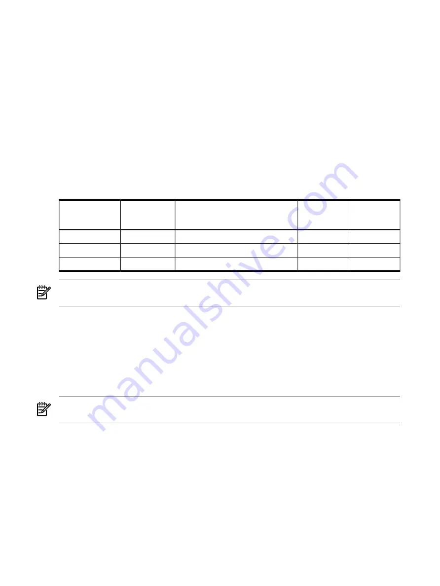
lists the server power states.
Table 1-17 Power States
DC Voltage
Applied?
Standby DC
Voltage
Applied?
Power Activated Through the iLO MP
PC
Command; or Front Panel Power Button
Activated?
Power Cable
Plugged Into
Receptacle?
Power States
No
Yes
No
Yes
Standby power
Yes
Yes
Yes
Yes
Full power
No
No
No
No
Off
NOTE:
If the power restore feature is set to Always On through the iLO MP
PR
command, the
server automatically powers on to the full power state.
Powering On the Server
Power on the server to full power using the following methods if the server is in the standby
power state:
•
iLO MP
PC
command
•
Power button
Powering On the Server Using the iLO MP
NOTE:
If the power restore feature is set to Always On through the iLO MP
PR
command, the
server automatically powers on to the full power state.
To power on the server using the iLO MP, follow these steps:
1.
Plug all power cables into the receptacles on the rear panel of the server.
2.
Initiate a console session, and access the
MP Main Menu
.
3.
To enable command mode, enter
CM
.
4.
To use the remote power control command, enter
PC
.
5.
To power on the server, enter
ON
.
6.
To confirm the action, enter
YES
when prompted.
7.
Start the operating system.
40
Overview
Summary of Contents for rp4410
Page 16: ...16 ...
Page 20: ...20 ...
Page 42: ...42 ...
Page 50: ...50 ...
Page 128: ...128 ...
Page 176: ...Figure 6 21 I O Baseboard Locking Lever 176 Removing and Replacing Components ...
Page 230: ...230 ...
Page 240: ...240 ...
Page 242: ...242 ...


