


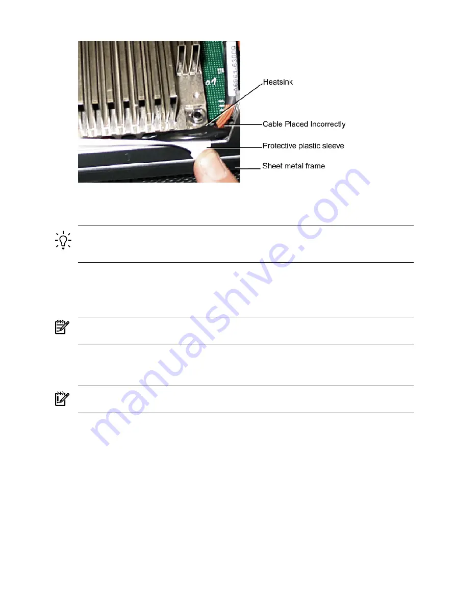
Figure 6-17 Processor Cable Placed Incorrectly
7.
Using the CPU Install Tool 2.5-mm Allen wrench, lock the assembly to the socket by rotating
the cam on the socket 180 degrees clockwise.
TIP:
When rotating the locking cam, hold the palm of your hand on top of the assembly
and exert light pressure. This ensures that the assembly stays flush and level to the socket
while it is being tightened.
8.
Plug the processor cable into its socket on the extender board.
9.
Place the sequencer frame over the processor.
10. Using your fingers, hand-tighten the two knurled thumbscrews on the sequencer frame just
until the screw stops turning.
NOTE:
Do not tighten the other four shoulder screws until you have first hand-tightened
the two knurled thumbscrews.
11. Using a CPU Install Tool (Torx T15 driver), tighten the four remaining T15 shoulder screws
until they just bottom out. Follow the tightening sequence shown in
the Dual Processor Module on the Processor Extender Board”
IMPORTANT:
Do not overtighten the four shoulder screws. They can shear off if
overtightened. Stop tightening the shoulder screws when you feel them just bottom out.
12. Using the Torx T15 driver, finish tightening the two thumbscrews.
170
Removing and Replacing Components
Summary of Contents for rp4410
Page 16: ...16 ...
Page 20: ...20 ...
Page 42: ...42 ...
Page 50: ...50 ...
Page 128: ...128 ...
Page 176: ...Figure 6 21 I O Baseboard Locking Lever 176 Removing and Replacing Components ...
Page 230: ...230 ...
Page 240: ...240 ...
Page 242: ...242 ...


