


Chapter 3
Installing Additional Components
Installing Graphics
40
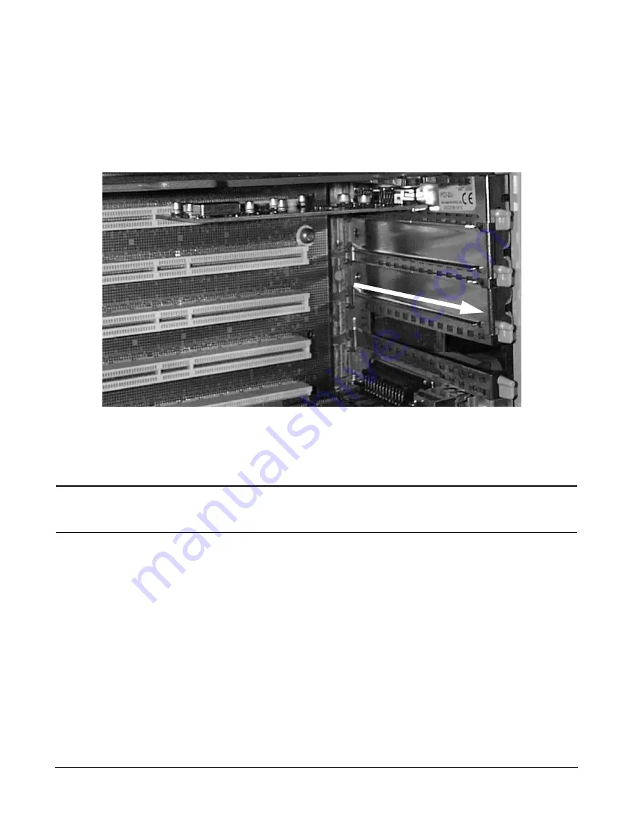
Step 5.
Grasp the handle on the right rear panel and remove the panel from the side of the chassis. The 12
PCI slots, numbered 1-12 from bottom to top, will be in view.
Step 6.
Remove the PCI slot cover from the slot that will receive the PCI card. To remove the PCI slot cover,
slide the PCI slot cover away from the server.
Step 7.
Center the graphics card within the space created by removing the PCI I/O slot cover. Slide the card
toward the edge connectors. Ensure the edge connectors on the card are in alignment with the
connectors of the slot. Apply pressure to the card until it snaps firmly in place. Repeat process for
USB card.
NOTE
The graphics card must be installed in any Turbo slot while the USB will work in any
slot. To reserve Turbo slots for high performance I/O cards, install the USB card in a
non-Turbo slot
Summary of Contents for L1000 - 9000 - 0 MB RAM
Page 7: ...Contents vii Typical Installation Schedule 207 Site Inspection 208 Delivery Survey 212 ...
Page 8: ...Contents viii ...
Page 10: ...Tables x ...
Page 12: ...Figures xii ...
Page 14: ...xiv ...
Page 16: ...Chapter 1 Server Overview 2 ...
Page 17: ...Chapter 2 3 2 Server Unpacking and Installation ...
Page 37: ...Chapter 3 23 3 Installing Additional Components ...
Page 60: ...Chapter 3 Installing Additional Components Installing Disk Drives 46 ...
Page 61: ...Chapter 4 47 4 Cable Connections ...
Page 91: ...Chapter 5 77 5 Utilities ...
Page 98: ...Chapter 5 Utilities Configuring the Rev B Guardian Service Processor GSP 84 ...
Page 99: ...Chapter 6 85 6 Troubleshooting ...
Page 134: ...Chapter 6 Troubleshooting Fan Power Supply and Disk LED States 120 ...
Page 189: ...Appendix A 175 A Parts and Accessories ...


