


Chapter 7
Removing and Replacing Components
Individual Component Remove/Replace Instructions
166
Display Board Removal
The Display Board contains the server’s ON/OFF switch and five LEDs that indicate server status when
power is applied.
CAUTION
The Display Board is not a HotSwap or HotPlug unit. Ensure that the server is powered-down
prior to removal.
To remove the Display Board, perform the following tasks:
1. Remove the three T-10 screws that hold the Display Board in place near the top of the chassis front.
2. Remove the two T-15 screws that hold the front Chassis Fan in place and extract the fan from the server.
3. Reach up through the top of the Chassis Fan cavity and carefully pull the Display Board back to free the
LEDs and the On/Off switch from their chassis openings. Pull the Display Board down through the
Chassis Fan cavity.
4. Disconnect the ribbon cable from the Display Board, and place the display board on a suitable work
surface.
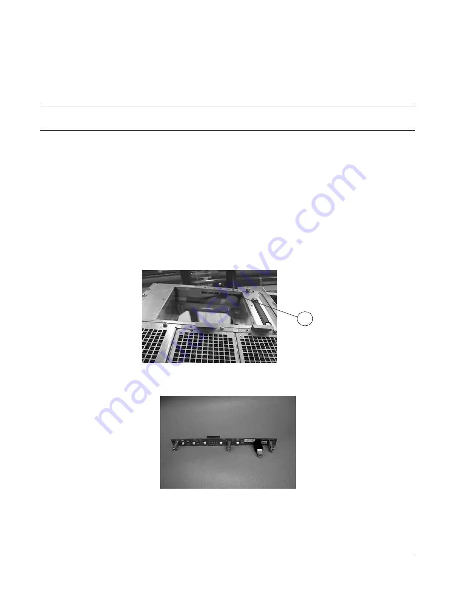
The following graphic shows the Display Board access location (item 1) (looking up from the bottom of the
front of the server).
The next graphic shows the Display Board module.
1
Summary of Contents for L1000 - 9000 - 0 MB RAM
Page 7: ...Contents vii Typical Installation Schedule 207 Site Inspection 208 Delivery Survey 212 ...
Page 8: ...Contents viii ...
Page 10: ...Tables x ...
Page 12: ...Figures xii ...
Page 14: ...xiv ...
Page 16: ...Chapter 1 Server Overview 2 ...
Page 17: ...Chapter 2 3 2 Server Unpacking and Installation ...
Page 37: ...Chapter 3 23 3 Installing Additional Components ...
Page 60: ...Chapter 3 Installing Additional Components Installing Disk Drives 46 ...
Page 61: ...Chapter 4 47 4 Cable Connections ...
Page 91: ...Chapter 5 77 5 Utilities ...
Page 98: ...Chapter 5 Utilities Configuring the Rev B Guardian Service Processor GSP 84 ...
Page 99: ...Chapter 6 85 6 Troubleshooting ...
Page 134: ...Chapter 6 Troubleshooting Fan Power Supply and Disk LED States 120 ...
Page 189: ...Appendix A 175 A Parts and Accessories ...


