


Chapter 3
Installing Additional Components
Installing Memory
25
Installing Memory
Memory Configuration Rules
rp54xx servers have 16 slots (8 DIMM pairs) for memory DIMMs. These slots are numbered 0a/b, 1a/b,... 7a/b.
8 of these slots (4a/b - 7a/b) are disabled on rp5400 servers. rp5450 servers can access all slots. rp5400 and
rp5450 servers have DIMM slots located on the System Board.
rp5470 servers install DIMMs using Memory Carriers. The Memory Carriers fit into slots on the System
Board.
The following rules govern the installation of memory DIMMs for rp5400, rp5450, and rp5470 servers:
•
Memory must be installed in DIMM pairs.
•
The capacity of DIMMs within a pair must be the same.
•
Install DIMMs with the greatest capacity in the lowest slot numbers.
•
Install DIMMs the following slot order: 0a/b, 1a/b, 2a/b, 3a/b, and so on.
Installing rp5400 and/or rp5450 DIMMs
Step 1.
Power down and
unplug
the rp54xx server.
CAUTION
DC voltages are present when the server is connected to AC power. Do not install or
service rp54xx internal components while DC voltage is present. Failure to observe
this precaution can result in damage to the server.
Step 2.
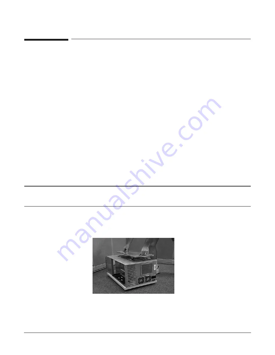
Loosen the captive T-15 screws that hold the top cover in place, then grasp the strap handle, raise
the cover slightly, and pull the cover toward the front of the server to free the cover tabs from the
slots in the chassis. The air baffle will be exposed.
Step 3.
Make the top of the server accessible for service.
Summary of Contents for L1000 - 9000 - 0 MB RAM
Page 7: ...Contents vii Typical Installation Schedule 207 Site Inspection 208 Delivery Survey 212 ...
Page 8: ...Contents viii ...
Page 10: ...Tables x ...
Page 12: ...Figures xii ...
Page 14: ...xiv ...
Page 16: ...Chapter 1 Server Overview 2 ...
Page 17: ...Chapter 2 3 2 Server Unpacking and Installation ...
Page 37: ...Chapter 3 23 3 Installing Additional Components ...
Page 60: ...Chapter 3 Installing Additional Components Installing Disk Drives 46 ...
Page 61: ...Chapter 4 47 4 Cable Connections ...
Page 91: ...Chapter 5 77 5 Utilities ...
Page 98: ...Chapter 5 Utilities Configuring the Rev B Guardian Service Processor GSP 84 ...
Page 99: ...Chapter 6 85 6 Troubleshooting ...
Page 134: ...Chapter 6 Troubleshooting Fan Power Supply and Disk LED States 120 ...
Page 189: ...Appendix A 175 A Parts and Accessories ...


