


Chapter 2
Server Unpacking and Installation
Install Stand-Alone Server in a Cabinet
17
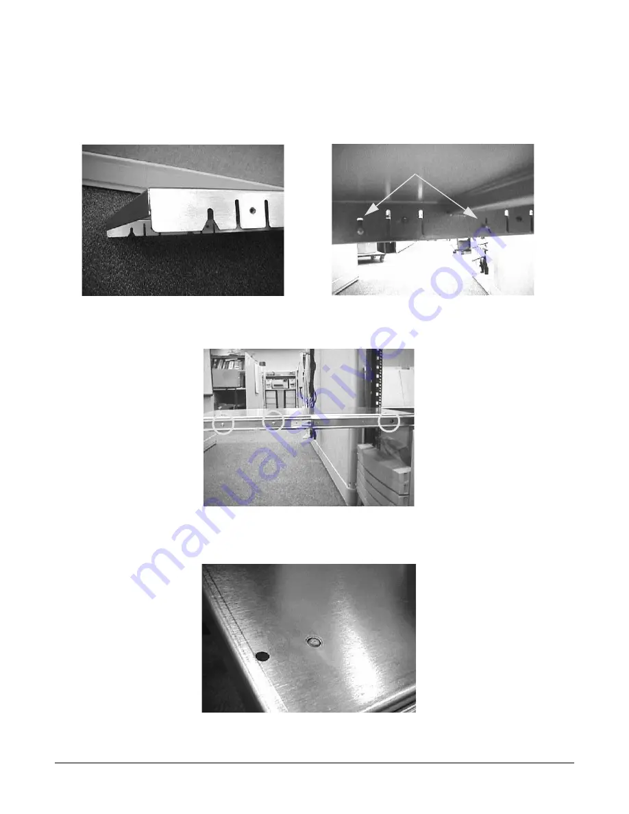
Step 12.
Take the tray and place it onto the pins that extend from the slides' inner members. The slots with
wide lead-in guides on the side of the tray fit down onto the slides' pins. The flat part of the tray will
be on top, and the mounting holes in the top of the tray will be located to the right of the center of
the tray. Slide the tray all the way down on both sides so that the pins reach the top of the slots in
the side of the tray.
Step 13.
Use six, M5 x 12 screws (without washers) to attach the tray to the slides. Three screws are used to
attach each slide. Insert the screws through the slides, through the tray and tighten into the
threaded nuts located on the inside of the sides of the tray.
Step 14.
From the bottom of the tray pull the plunger pin down and give it a 1/4 turn to hold it in place.
Pins in Slots
3 Pan Head
M5x12 T25 screws
on each side
Summary of Contents for L1000 - 9000 - 0 MB RAM
Page 7: ...Contents vii Typical Installation Schedule 207 Site Inspection 208 Delivery Survey 212 ...
Page 8: ...Contents viii ...
Page 10: ...Tables x ...
Page 12: ...Figures xii ...
Page 14: ...xiv ...
Page 16: ...Chapter 1 Server Overview 2 ...
Page 17: ...Chapter 2 3 2 Server Unpacking and Installation ...
Page 37: ...Chapter 3 23 3 Installing Additional Components ...
Page 60: ...Chapter 3 Installing Additional Components Installing Disk Drives 46 ...
Page 61: ...Chapter 4 47 4 Cable Connections ...
Page 91: ...Chapter 5 77 5 Utilities ...
Page 98: ...Chapter 5 Utilities Configuring the Rev B Guardian Service Processor GSP 84 ...
Page 99: ...Chapter 6 85 6 Troubleshooting ...
Page 134: ...Chapter 6 Troubleshooting Fan Power Supply and Disk LED States 120 ...
Page 189: ...Appendix A 175 A Parts and Accessories ...


