


Chapter 3
Installing Additional Components
Installing Memory
28
Installing rp5470 DIMMs
DIMMs for the rp5470 system are installed in memory carriers instead of the system board, as are the other
rp54xx systems. However, rp5470 memory carriers are also located on the system board, so the method for
opening and closing the system is the same. Procedures for removing and replacing the server top and baffle
are listed below, without the pictures shown in the section titled, “
Installing rp5400 and/or rp5450 DIMMs
.”
If you wish to reveiw the pictures, please refer to the aforementioned section.
Step 1.
Power down and unplug the rp54xx server.
NOTE
DC voltages are present when the server is connected to AC power. Do not attempt to
install or service: CPUs, Memory, PSMs, the Platform Monitor or PCI I/O cards
installed in non-Turbo slots (1-6) while DC voltage is present. Failure to observe this
warning may result in damage to the server.
Step 2.
Make the top of the server accessible for service.
Step 3.
Loosen the captive T-15 screws that hold the top cover in place, then grasp the strap handle, raise
the cover slightly, and pull the cover toward the front of the server to free the cover tabs from the
slots in the chassis. The air baffle will be exposed.
Step 4.
Loosen the four (4) captive T-15 screws on the air baffle. Grasp the two handles on the baffle, and
lift and remove the baffle.
Step 5.
Observe Electrostatic Discharge (ESD) precautions.
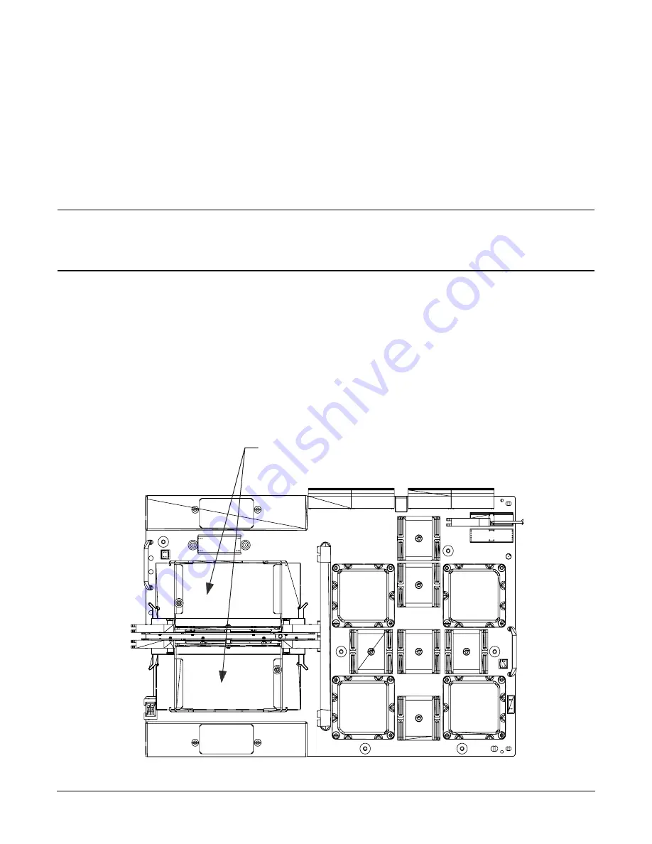
Step 6.
Refer to the following graphic for Memory Carrier locations.
Memory Carrier Assemblies
Summary of Contents for L1000 - 9000 - 0 MB RAM
Page 7: ...Contents vii Typical Installation Schedule 207 Site Inspection 208 Delivery Survey 212 ...
Page 8: ...Contents viii ...
Page 10: ...Tables x ...
Page 12: ...Figures xii ...
Page 14: ...xiv ...
Page 16: ...Chapter 1 Server Overview 2 ...
Page 17: ...Chapter 2 3 2 Server Unpacking and Installation ...
Page 37: ...Chapter 3 23 3 Installing Additional Components ...
Page 60: ...Chapter 3 Installing Additional Components Installing Disk Drives 46 ...
Page 61: ...Chapter 4 47 4 Cable Connections ...
Page 91: ...Chapter 5 77 5 Utilities ...
Page 98: ...Chapter 5 Utilities Configuring the Rev B Guardian Service Processor GSP 84 ...
Page 99: ...Chapter 6 85 6 Troubleshooting ...
Page 134: ...Chapter 6 Troubleshooting Fan Power Supply and Disk LED States 120 ...
Page 189: ...Appendix A 175 A Parts and Accessories ...


