


Chapter 2
Server Unpacking and Installation
Stationary L-Bracket Rail Assembly
21
Installing Stationary Rails
The installation of stationary rails is similar for most cabinet and rail combinations.
The key considerations to are:
•
Ensure that all safety precautions are read, understood, and observed
•
Follow all installation instructions provided with the cabinet and rail kits, and
•
Ensure that the rails extend out from the cabinet posts sufficiently to properly and safely support the
equipment being installed.
To install an rp54xx server on stationary rails in an approved cabinet proceed as follows:
Step 1.
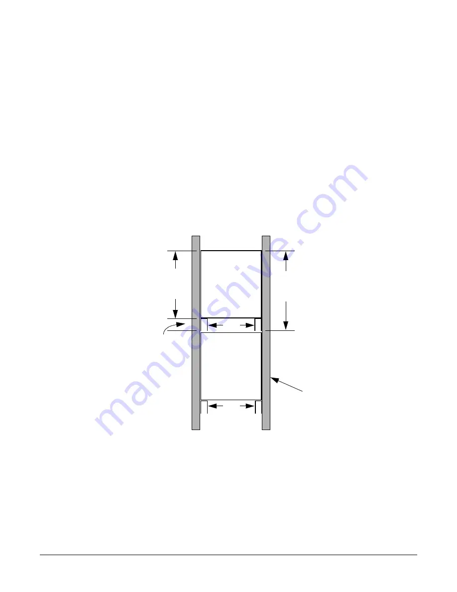
Locate the rail mounting height in the cabinet. Allow for the following space requirements:
•
For each rp54xx server, allow 31.8cm (12.5 inches) vertically (7 EIAs or Rack Units (RUs).
•
If installing the A5575A rail kit, allow an
additional
vertical 4.45cm (1.75 inches (1 EIA) each
set of rails.
Step 2.
Install sheet metal nut(s) in the vertical cabinet posts at the required height for the kit being
installed:
•
Install the first nut either:
— 4.45 cm (1.75 Inches) above the top, or
— 31.8 cm (12.5 inches) below the bottom of the last server.
•
If installing a A5562A rail kit, install the second nut in the next frame hole below the first.
Step 3.
Hold the rail in place and insert and tighten the screws.
rp54xx
Server
31.8 cm
(12.5
inches
Rail
31.8 cm
(14.25
inches
rp54xx
Server
Rail
4.45 cm
(1.75
Inches
A5575A Rail Kit
in approved
Non- E-Series
cabinet shown
Summary of Contents for L1000 - 9000 - 0 MB RAM
Page 7: ...Contents vii Typical Installation Schedule 207 Site Inspection 208 Delivery Survey 212 ...
Page 8: ...Contents viii ...
Page 10: ...Tables x ...
Page 12: ...Figures xii ...
Page 14: ...xiv ...
Page 16: ...Chapter 1 Server Overview 2 ...
Page 17: ...Chapter 2 3 2 Server Unpacking and Installation ...
Page 37: ...Chapter 3 23 3 Installing Additional Components ...
Page 60: ...Chapter 3 Installing Additional Components Installing Disk Drives 46 ...
Page 61: ...Chapter 4 47 4 Cable Connections ...
Page 91: ...Chapter 5 77 5 Utilities ...
Page 98: ...Chapter 5 Utilities Configuring the Rev B Guardian Service Processor GSP 84 ...
Page 99: ...Chapter 6 85 6 Troubleshooting ...
Page 134: ...Chapter 6 Troubleshooting Fan Power Supply and Disk LED States 120 ...
Page 189: ...Appendix A 175 A Parts and Accessories ...


