


Chapter 7
Removing and Replacing Components
Individual Component Remove/Replace Instructions
149
HotPlug Disk Drive Replacement
The internal disk drives (up to four) are located at the front right side of the server (as you are facing it).
When proper software and hardware procedures are followed, internal disk drives can be removed and
replaced while the server is running.
CAUTION
Disk Drives can be removed or installed with the server still powered on. This is referred to as
a “manual HotPlug”.
However, DO NOT replace a HotPlug disk drive until a controlled shutdown of the operating
system has been performed.
Hardware HotPlug Procedure
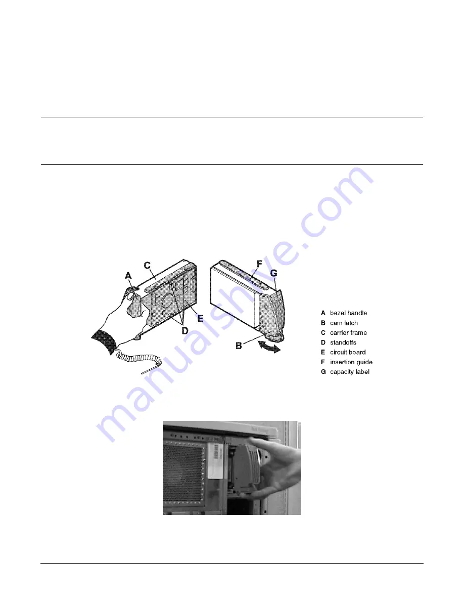
To replace a disk drive in the server, grasp the tab at the bottom of the cam latch on the selected disk drive,
push the button inside the cam latch, and pull the cam latch out and up. The disk drive will unlock. Pull
gently until it slides completely free.
The following graphic shows disk features.
The next graphic depicts disk removal/replacement.
Summary of Contents for L1000 - 9000 - 0 MB RAM
Page 7: ...Contents vii Typical Installation Schedule 207 Site Inspection 208 Delivery Survey 212 ...
Page 8: ...Contents viii ...
Page 10: ...Tables x ...
Page 12: ...Figures xii ...
Page 14: ...xiv ...
Page 16: ...Chapter 1 Server Overview 2 ...
Page 17: ...Chapter 2 3 2 Server Unpacking and Installation ...
Page 37: ...Chapter 3 23 3 Installing Additional Components ...
Page 60: ...Chapter 3 Installing Additional Components Installing Disk Drives 46 ...
Page 61: ...Chapter 4 47 4 Cable Connections ...
Page 91: ...Chapter 5 77 5 Utilities ...
Page 98: ...Chapter 5 Utilities Configuring the Rev B Guardian Service Processor GSP 84 ...
Page 99: ...Chapter 6 85 6 Troubleshooting ...
Page 134: ...Chapter 6 Troubleshooting Fan Power Supply and Disk LED States 120 ...
Page 189: ...Appendix A 175 A Parts and Accessories ...


