


Chapter 2
Server Unpacking and Installation
Install Stand-Alone Server in a Cabinet
14
Step 3.
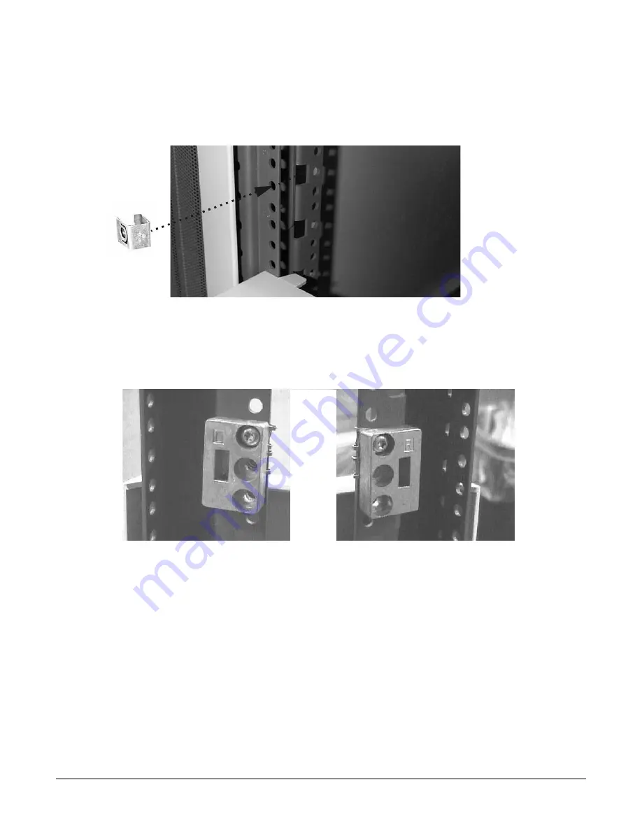
On the front vertical mounting posts
only
, slide M5 sheet metal nuts onto the posts over the holes
immediately adjacent to the vertical slots determined in the previous step. Also place M5 sheet
metal nuts on the holes directly above these. Orient the sheet metal nuts so that the threaded
portion faces towards the outside of the cabinet. There should now be a total of four (4) sheet metal
nuts installed.
Step 4.
If the cabinet is a non-E-Series cabinet, discard the left hand and right hand aluminum spacers and
two of the M5 x 16 screws with cress-cup washers and proceed to step 12.
Step 5.
If the cabinet is an E-Series cabinet, place the hook of the aluminum spacer marked “L” (5183-1864)
into the appropriate vertical, rectangular slot on the front, left hand mounting post. The hook
points downward. Similarly, place the spacer marked “R” (5183-1863) into the appropriate slot on
the right hand mounting post.
Step 6.
Use one M5 x 16 screw with cress-cup washer to attach each spacer to its vertical post. Do this by
inserting the screw through the top hole in the spacer, through the mounting rail and tightening it
into the sheet metal nut located at that position.
Step 7.
Take the left hand slide/bracket assembly (marked 337079-1L) and install it into the left hand
vertical mounting posts. This is done by inserting the pin at the rear of the slide's mounting bracket
into the 23rd hole in the rear vertical mounting post and inserting the hook at the front of the
Summary of Contents for L1000 - 9000 - 0 MB RAM
Page 7: ...Contents vii Typical Installation Schedule 207 Site Inspection 208 Delivery Survey 212 ...
Page 8: ...Contents viii ...
Page 10: ...Tables x ...
Page 12: ...Figures xii ...
Page 14: ...xiv ...
Page 16: ...Chapter 1 Server Overview 2 ...
Page 17: ...Chapter 2 3 2 Server Unpacking and Installation ...
Page 37: ...Chapter 3 23 3 Installing Additional Components ...
Page 60: ...Chapter 3 Installing Additional Components Installing Disk Drives 46 ...
Page 61: ...Chapter 4 47 4 Cable Connections ...
Page 91: ...Chapter 5 77 5 Utilities ...
Page 98: ...Chapter 5 Utilities Configuring the Rev B Guardian Service Processor GSP 84 ...
Page 99: ...Chapter 6 85 6 Troubleshooting ...
Page 134: ...Chapter 6 Troubleshooting Fan Power Supply and Disk LED States 120 ...
Page 189: ...Appendix A 175 A Parts and Accessories ...


