Index
Index - 2
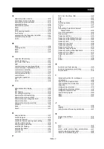
M
main circuit terminal ............................................ 2-7
major failure signal ........................................... 4-40
manual torque boost ......................................... 4-48
MI1, MI2, MI3, MI4, MI5, MI6, MI7, MI8 ............ 4-37
MO1, MO2, MO3, MI4, MO5, MO6 ................... 4-41
MJA .................................................................. 4-40
Modbus ............................................................. 4-45
monitor mode ...................................................... 4-2
motor constant .................................................. 4-48
motor gear ratio ................................................ 4-32
multispeed command ...................................... 4-15
multistage position switching ............................ 4-37
N
NDc .................................................................. 4-41
NO/NC .............................................................. 4-35
O
OHF .................................................................. 4-40
OL, OL2 ............................................................ 4-40
OLR .................................................................. 4-36
online auto-tuning ............................................. 4-46
operation after option error ............................... 4-31
operation frequency .......................................... 4-13
operation mode ................................................. 4-33
operation time over signal
(RNT)/plug-in time over signal
(ONT) .......................................................... 4-40
overcurrent suppress ........................................ 4-29
overload restriction ........................................... 4-29
overvoltage suppresion .................................... 4-29
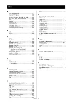
P
PIDl ................................................................... 4-22
Position contrl ................................................... 4-18
Pre set position ................................................. 4-18
R
Restart operation .............................................. 4-14
Resonant frequency avoidance ........................ 4-21
Run command selection ................................... 4-14
Run command direction restriction ................... 4-14
running signal ................................................... 4-41
RV ...................................................................... 5-3
RVR .................................................................. 4-40
S
scaled output frequency monitoring .................. 4-15
sensorless vector control .................................. 4-14
servo-on ......................................................... 4-112
SET, SET3 ........................................................ 4-51
SFT ................................................................... 4-36
SF1, SF2, SF3, SF4, SF5, SF6, SF7 ................ 4-36
SLV ................................................................... 4-50
software lock ..................................................... 4-59
SPD .................................................................. 4-37
Speed limit for torque control ............................ 4-17
speed/position switching ................................... 4-37
STA ................................................................... 4-37
STP .................................................................. 4-58
T
Temporary frequency addition ............................ 4-3
test run ............................................................... 1-3
thermistor ......................................................... 2-21
THM ................................................................. 4-40
3-wire input....................................................... 4-14
torque biasing ................................................... 4-17
torque boost ..................................................... 4-48
torque control ................................................... 4-17
torque limitation ................................................ 4-28
torque monitoring ............................................. 4-10
troubleshooting ................................................... 5-1
TRQ ................................................................... 5-4
TRQ1, TRQ2 .................................................... 4-36
2-stage acceleration/deceleration .................... 4-36
2CH .................................................................. 4-36
U
UDC ................................................................. 4-36
unattended start protection .............................. 4-36
user monitor ...................................................... 4-11
user parameter ................................................. 4-59
USP .................................................................. 4-36
UV .................................................................... 4-40
V
vector control with encoder .............................. 4-14
W
WAC ................................................................. 4-40
WAF ................................................................. 4-40
window comparator .......................................... 4-44
Z
0Hz detection signal ......................................... 4-41
0Hz speed detection signal .............................. 4-44
zero-return function .......................................... 4-19
ZS .................................................................... 4-41
Summary of Contents for P1-00041HFEF
Page 6: ...0 5 Contents Contents Memo ...
Page 42: ...2 26 Chapter 2 Installation and Wiring Memo ...
Page 129: ...Index Index 3 memo ...
Page 130: ...Index Index 4 memo ...

