2-20
Chapter 2
Installation and Wiring
■
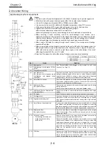
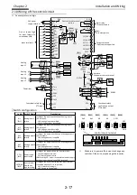
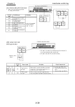
Output terminals
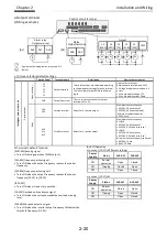
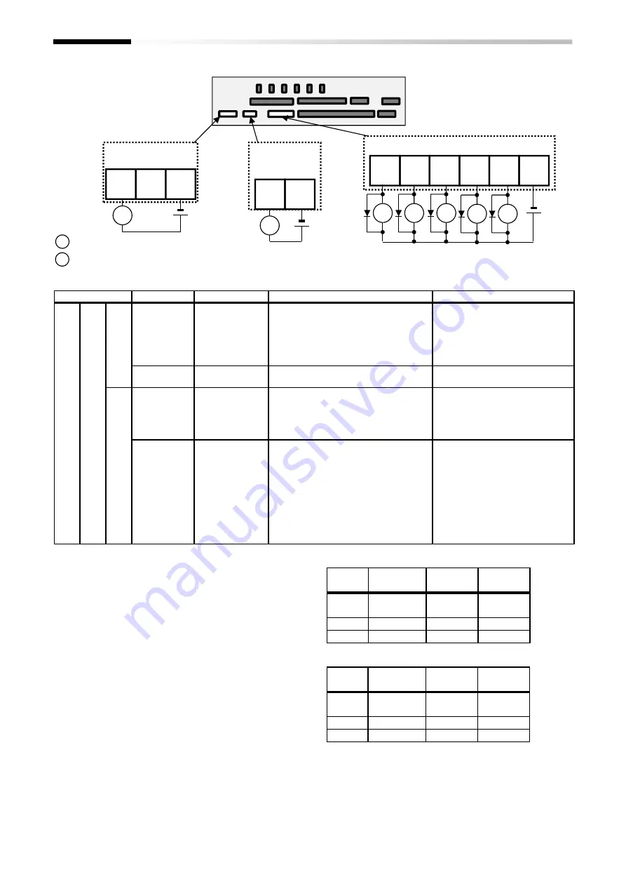
(Wiring example)
[AL]
[ZS]
: Equipment including lamps, relays and PLC
: Relays
• [] it means factory default settings.
■
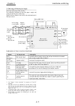
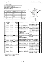
Terminal’s default function
[RUN:001]Running signal
• Turns ON during operation (PWM output).
[FA1:002]Frequency-arrival signal
• Turns ON when the output frequency reaches the control
frequency.
[FA1:003]Frequency-arrival signal 2
• Turns ON when the output frequency reaches the control
frequency [CE-10] to [CE-13].
[IRDY:007]
• Turns ON when is ready for operation.
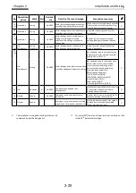
[OL:035]Overload notice advance signal
• Turns ON when the current exceeds the overload warning
level.
[ZS:040]0Hz speed detection signal
• Turns ON when the inverter output frequency falls below the
threshold frequency [CE-33].
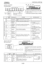
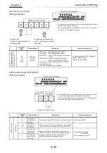
[AL:017]Operation
• In case of [CC-17]=00 (factory setting)
Power
supply
Status
AL0-AL1
AL0-AL2
ON
Normal
operation
Open
Closed
ON
Tripping
Closed
Open
OFF
–
Open
Closed
• In case of [CC-17]=01
Power
supply
Status
AL0-AL1
AL0-AL2
ON
Normal
operation
Closed
Open
ON
Tripping
Open
Closed
OFF
–
Open
Closed
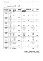
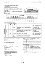
Terminal label
Terminal name
Description
Electric characteristics
In
te
ll
ig
e
n
t
o
u
tp
u
t
te
rm
in
a
ls
D
ig
it
a
l
o
u
tp
u
t
O
p
e
n
c
o
ll
e
ct
o
r
15
14
13
12
11
Output terminal
Terminal functions are selectable according
to the parameter settings for each terminal.
This is available for both SINK and Source
logics.
Open collector output
Between each terminal and CM2
• Voltage drop when turned on: 4 V
or less
• Max. allowable voltage 27V
• Max. allowable current 50mA
CM2
Output (common)
This is a common terminal for output
terminals 11 to 15.
R
e
la
y
16A
16C
1a relay terminal
Relays for A contact output
Maximum contact capacity
• AC250V, 2A(resistance)
• AC250V, 1A(inductive load)
(Minimum contact capacity)
• DC1V, 1mA
AL0
AL1
AL2
1c relay terminal
Relays for C contact output
Maximum contact capacity
AL1/AL0:
• AC250V, 2A(resistance)
• AC250V, 0.2A(inductive load)
AL2/AL0:
• AC250V, 1A(resistance)
• AC250V, 0.2A(inductive load)
Minimum contact capacity (common)
• AC100V, 10mA
• DC5V, 100mA
11
[FA1]
12
[RUN]
13
[OL]
14
[OTQ]
15
[WAF]
CM2
Output
RY
RY
RY
RY
RY
AL2
AL1
AL0
Alarm relay
Output terminal
X
X
16A
16C
Relay
Output terminal
X
RY
Control circuit terminal
Summary of Contents for P1-00041HFEF
Page 6: ...0 5 Contents Contents Memo ...
Page 42: ...2 26 Chapter 2 Installation and Wiring Memo ...
Page 129: ...Index Index 3 memo ...
Page 130: ...Index Index 4 memo ...

