background image

7. RESTORING THE FACTORY-SHIPPED CONDITION USING A RECOVERY DVD 

7-6 


4. 

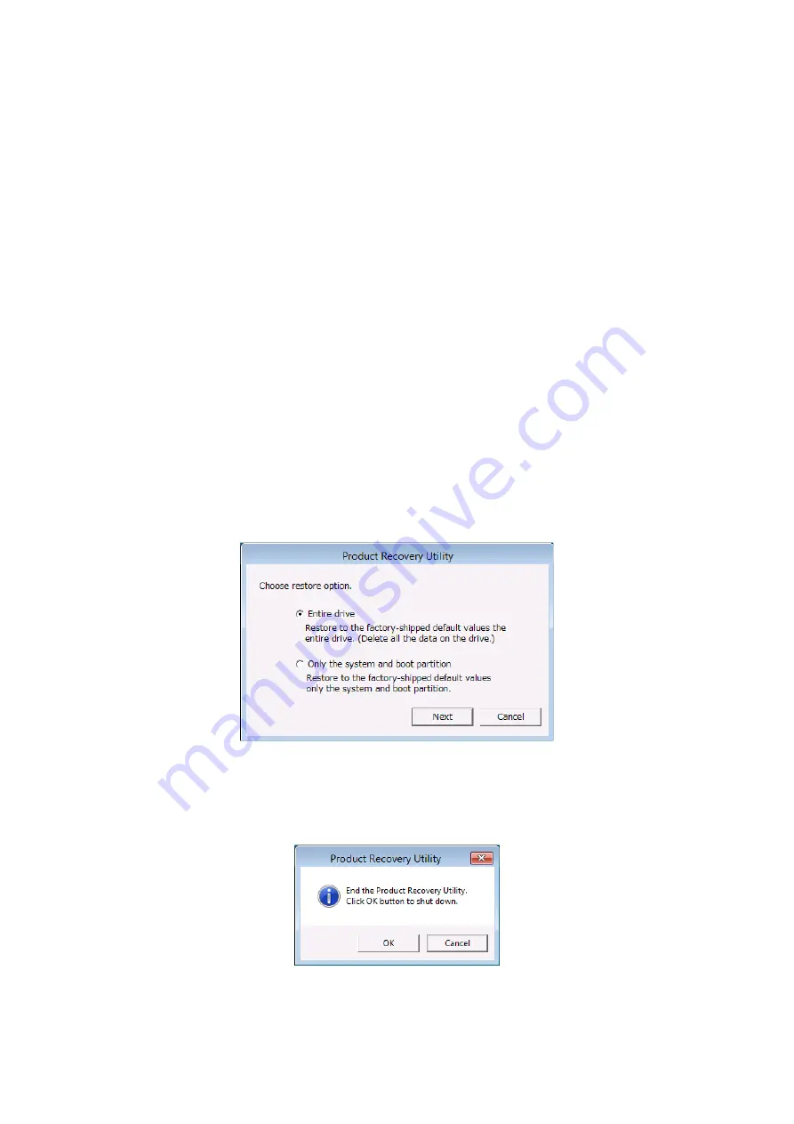
If you click Yes in the confirmation window, the selection window for the drive restoration options appears. 

• 

To restore the system drive to the factory-shipped condition, select a restoration option, and then click Next

• 

To cancel restoration of the system drive to the factory-shipped condition, click Cancel


Entire drive

Select this option if you want to restore the entire system drive to the factory-shipped condition, or if you 

want to configure a new drive to the factory-shipped condition after you replace the system drive. 

If you select this option and click Next, proceed to step 5. 


Only the system and boot partition

Select this option if the system drive has partitions other than the boot partition (the partition on which 

Windows is installed) for data storage or other purposes, and you want to restore the system drive to the 

factory-shipped condition while keeping these partitions. If you select this option, only the boot partition is 

restored to the factory-shipped condition. 

If you select this option and click Next, proceed to step 6. 

You cannot select this option in the following cases: 


The system drive has no boot partitions. 


The system drive has more than one boot partition. 


The size of the boot partition is less than the minimum boot partition size defined for the equipment. 

(For the HF-W2000 Model 58/55/50, the minimum size is 100 GB.) 


No array is built (for the B model only). 


If you click Cancel, the following message appears. Click OK. The recovery DVD is automatically ejected, 

and then the equipment automatically shutdown. 

To return the selection window for the drive restoration options, click Cancel


Summary of Contents for HF-W2000 50

Page 1: ... COMPUTER HF W2000 Model 58 55 50 INSTRUCTION MANUAL WIN 62 0073 03 Read and retain this manual Read safety instructions carefully and ensure that you understand them before beginning operations Keep this manual on hand for reference ...

Page 2: ...ed to Windows 10 2019 LTSC and Windows Server 2016 Standard is abbreviated to Windows Server 2016 Documentation structure The documentation for the HITACHI INDUSTRIAL COMPUTER HF W2000 MODEL 58 55 50 consists of the following SAFETY INSTRUCTIONS appended to this manual INSTRUCTION MANUAL this manual RAS FEATURES MANUAL downloaded from the site given in the contact information on the following page...

Page 3: ... other countries Intel Xeon Intel CoreTM and Celeron are trademarks of Intel Corporation in the United States and other countries DisplayPort and DisplayPort Certified Logo are registered trademarks of the Video Electronics Standards Association Magic PacketTM is a trademark or registered trademark of Advanced Micro Devices Inc All other product names of software and hardware described in this man...

Page 4: ...tablish a systematic schedule for backing up files Harmonic current standards This equipment complies with the JIS C 61000 3 2 harmonic current standard VCCI notice This is a Class A product based on the standard of the Voluntary Control Council for Interference by Information Technology Equipment VCCI If this equipment is used in a household environment electronic interference might occur In such...

Page 5: ...tual hardware environment provided by Virtual PC or Hyper V Host OS A base operating system that runs a virtual machine Guest OS An operating system that runs on a virtual machine Substituting terms This manual describes the operating procedures for Windows The names of the operations sign in and sign out are interchangeable with log on and log off respectively depending on the type of Windows Sub...

Page 6: ...o result in serious personal injury or death WARNING This symbol is used to indicate potential hazards that might result in serious personal injury or death CAUTION This symbol is used to indicate potential hazards that might result in minor or moderate personal injury NOTICE This symbol is used to indicate hazards that might result in equipment or property damage but not personal injury The headi...

Page 7: ...tric shock This equipment contains built in hard disk drives Do not hit the equipment or subject the equipment to shocks or vibrations because doing so might cause the equipment to fail If you drop the equipment or damage its chassis unplug the power cord from the outlet and then contact maintenance personnel Using faulty equipment without repairing it might result in a fire or an electric shock D...

Page 8: ...equipment Be careful to avoid personal injury when unpacking or carrying the equipment such as catching or hitting your fingers Before cleaning or replacing the dust filter of this equipment shutdown the OS unplug the power cord from the outlet and wait for at least one minute Failure to do so might result in injuries to the hands or fingers ...

Page 9: ... of the tapped hole to avoid adding too much torque and damaging the thread This equipment is evaluated assuming the use of the hardware specified in this manual Accordingly use only the specified hardware when upgrading options or replacing components If any other hardware is used for upgrades or replacements the equipment is not guaranteed to operate correctly Do not use the equipment in an envi...

Page 10: ...em immediately Note that if the power supply is cut the system might not be able to recover automatically If you insert or access a CD or DVD the system load might increase and running applications might be affected Do not insert or access a CD or DVD during online operation system operation When you finish accessing a CD or DVD eject the disc from the DVD drive Leaving it in the DVD drive might r...

Page 11: ...roperly grounded In addition you must install and use an earth leakage circuit breaker Failure to take these measures might result in fire or electric shock Do not use a two prong plug without a ground pole because doing so might result in electric shock or equipment failure Page 1 13 If any of the air intake and exhaust holes of the equipment are blocked the temperature inside the equipment might...

Page 12: ... extension board shutdown the OS unplug the power cord and wait for at least one minute Installing or removing an extension board without shutting down the power might result in an electric shock or a fire Page 6 10 Before you install or remove the main memory shutdown the OS unplug the power cord and wait for at least one minute Installing or removing the main memory without shutting down the pow...

Page 13: ...ovided with the equipment and place the equipment with the vertical stand on a level surface Page 1 13 Page 6 21 Before you clean or replace the dust filter of this equipment shutdown the OS unplug the power cord and wait for at least one minute Failure to do so might result in injury to the hands or fingers Page 6 1 When installing or removing components do not directly touch parts inside the equ...

Page 14: ...so might result in an explosion a fire a burst battery heat generation a liquid spill or gas generation Install the battery by using the correct polarity Using the wrong polarity might cause an abnormal reaction such as charging or shorting resulting in a liquid spill heat generation or a burst battery Page 6 22 When installing or removing a jumper socket do not directly touch parts inside the equ...

Page 15: ...acteristics of the inrush current restraint method that is used with this equipment inrush currents might increase more than usual if the power is turned on before the power supply unit has sufficiently and naturally cooled after the power is turned off After turning off the power wait at least one minute before turning on the power again If you do not do so inrush currents might affect the breake...

Page 16: ... remote device is on If you do so a short circuit between the power supply and the ground might cause a failure in the equipment If an interface cable comes off while the power for the equipment is on shutdown the OS and unplug the power cord Unplugging the power cord without shutting down the OS might destroy internal files When you connect a cable for external contacts connect the cable to a con...

Page 17: ...ct the disc from the DVD drive Leaving it in the DVD drive might result in a failure Leaving the disc tray open might result in a failure Close the disc tray when it is not in use Do not use a CD or DVD that is not balanced due to attached labels or other differences a disc with cracks scratches or vertical deviation or a disc with a non standard shape Using such a disc might generate an abnormal ...

Page 18: ...he container has been damaged or broken Doing so might damage the equipment Page 6 1 After washing a dust filter dry it completely before re attaching it to the equipment Using the equipment while its dust filter is not completely dry might cause equipment failure When using a detergent to clean a dust filter use a neutral detergent Using other types of detergents might cause the dust filter to lo...

Page 19: ...s Performing these actions might result in failure of the equipment or drive Before replacing an HDD or SSD shutdown the OS unplug the power cord and wait for at least one minute Install or remove an HDD or SSD only when necessary for example when you need to replace an HDD or SSD due to a failure Performing these actions frequently might result in failure of the equipment or drive Fully insert HD...

Page 20: ...nufacturer Replace HDDs by using only the specific items specified by the manufacturer Failure to do so might result in existing data on the HDD being lost In addition always observe the recommended replacement interval for HDDs See APPENDIX HANDLING OF REPLACEABLE COMPONENTS Each unit of equipment has its own RAID1 configuration information such as a serial number As such you cannot use HDDs by s...

Page 21: ...bjecting an HDD to shocks might result in drive failure Until rebuilding is complete avoid shutting off the power to this equipment or installing and removing HDDs Performing these actions might result in data on the HDDs being lost or a failure Page 10 10 If you apply the recovery method for an offline HDD to an HDD that was set to offline by something other than the RAS software the HDD might no...

Page 22: ...sult in data stored on an HDD being lost Do not use an HDD previously used in any model as a replacement HDD If you do this equipment might not operate properly or the data on the HDDs might be lost because of configuration information mismatches or other reasons Do not replace two HDDs at the same time Doing so might result in data corruption When replacing an HDD set the HDD to offline mode in t...

Page 23: ...S 18 SAFETY INSTRUCTIONS Continued WARNING Labels The warning labels are attached to the following positions on the equipment Label Label ...

Page 24: ...look into the laser beam whether directly or indirectly Doing so might result in visual impairment NOTICE Label The notice label is attached to the following position on the equipment Label CLASS 3B VISIBLE AND INVISIBLE LASER RADIATION WHEN OPEN AND INTERLOCKS DEFEATED AVOID EXPOSURE TO THE BEAM Label ...

Page 25: ...rective 2006 66 EC This symbol mark is valid in European Union countries This symbol mark is specified in Article 20 Information for end users and Annex II of EU Directive 2006 66 EC This equipment contains a lithium battery When removing the battery follow the instructions in 6 4 Removing the Lithium Battery In the European Union a separate collection system for used batteries and accumulators is...

Page 26: ... affect the breaker connected to the equipment and the life span of the equipment itself 1 Transporting the equipment Required actions When transporting or carrying the equipment pack it by using the dedicated container the container and packing materials used when the equipment was delivered When transporting or carrying the equipment in a chassis protect the equipment so that any vibrations and ...

Page 27: ... AC prepare a power cord that is compatible with the input voltage to be used Install Class D grounding previously known as Class 3 grounding as defined in the Technical Standard for Electrical Facilities of Japan to maintain normal operation of electronic circuits containing highly integrated LSIs and to protect devices from abnormal voltage caused by lightning strikes or other causes Use a power...

Page 28: ...r the screen might black out In such cases turn off the power to the equipment and then turn the power back on 5 Installation environment Precautions When you install a commercially available device in an extension slot you must meet the specifications of the required environment for both the commercially available device and this equipment See 1 6 1 Environment When you install an extension board...

Page 29: ...s or on a desk take into consideration the temperature increase around the equipment The system clock and similar operations inside the equipment always operate by using a backup battery even when the power is off Therefore if you store the equipment at a temperature outside the operating temperature range you might need to reconfigure the clock settings and other system BIOS settings when you sta...

Page 30: ...dby lamp of the equipment is on If you receive a Magic PacketTM frame when the power is about to be turned off after an OS shutdown the equipment might restart without being turned off or Wake on LAN WOL might not function at all See 2 7 2 Turning on the power by using a LAN Specifications Depending on the status of the network Magic PacketTM frames might be lost To avoid this set up the system so...

Page 31: ... connection configuration for the displays reconfigure the screen settings accordingly Depending on the application software the screen might flicker and video playback might not be smooth The multi streaming function of DisplayPort daisy chaining is not supported If a display connected via a DisplayPort connection is turned off the display can no longer be detected Required actions If you want to...

Page 32: ...eir degraded performance at high or low temperatures do not cause problems in user applications Required actions Do not subject HDDs or SSDs to vibrations or shocks Take preventive action against static electricity due to human contact and other activities in the workplace Hold the bracket or sides of an HDD or SSD Do not touch the printed circuit board or connectors When you store an HDD or SSD f...

Page 33: ...bled the equipment might not be able to read from or write to the CD or DVD properly Depending on the write quality of a CD or DVD or the read characteristics of the DVD drive data that was written by other devices might not be readable on this equipment and data that was written by this equipment might not be readable on other devices 2 Handling CDs or DVDs Precautions Do not apply benzene thinne...

Page 34: ...le For details about cable length see 5 8 3 External interface cable length specifications Required actions When using a USB port check the orientation of the USB connector and then insert the connector slowly to avoid damaging the USB port When a USB device is inserted removed or accessed the system load might increase If you need to use a USB device during online operation system operation you m...

Page 35: ...ke appropriate measures to protect the equipment 10 BIOS settings Specifications As long as an AC disconnection does not occur the BIOS settings are retained even if the backup battery runs out of power or is not installed After an AC disconnection the BIOS settings will return to the default settings after system startup but the OS always starts regardless of the After AC Power On setting If you ...

Page 36: ...l in the maintenance contract and pay the required maintenance fee as defined by the maintenance support level 12 Windows Settings 1 Applying hotfixes and other updates Specifications Users are responsible for applying any necessary hotfixes Windows Update or the latest service packs Verify system operation thoroughly to evaluate how the system will be affected by any applied hotfixes Windows Upda...

Page 37: ...C 12 This page is intentionally left blank ...

Page 38: ... 2 2 3 Shutting Down the Equipment 2 3 2 4 Shutting Down the Power 2 4 2 5 Emergency Shutdown 2 4 2 6 DVD Drive 2 5 2 6 1 Inserting an optical disc CD or DVD 2 5 2 6 2 Ejecting an optical disc CD or DVD 2 6 2 6 3 Using the DVD drive when the equipment is installed vertically 2 6 2 7 Controlling the Power By Using a LAN 2 7 2 7 1 Enabling the Wake on LAN WOL feature 2 7 2 7 2 Turning on the power b...

Page 39: ...terrupts 5 9 5 5 Serial Port Settings 5 10 5 6 BIOS Setup 5 11 5 7 Hardware System Clock 5 18 5 8 Interface Specifications 5 19 5 8 1 Connector specifications 5 19 5 8 2 External contact specifications 5 25 5 8 3 External interface cable length specifications 5 29 CHAPTER 6 INSPECTION AND MAINTENANCE 6 1 6 1 Daily Inspections 6 1 6 2 Periodic Inspections 6 4 6 3 Installing and Removing Components ...

Page 40: ... the settings related to memory dumps 8 9 8 3 Suppressing Startup Upon Detection of a Serious Failure 8 11 8 4 Maintenance Operation Commands 8 12 8 4 1 Log information collection command logsave 8 13 8 4 2 Memory dump file copy command mdump 8 15 8 4 3 Disk space allocation command for saving a memory dump createdmp 8 17 8 4 4 RAS information display command getrasinfo 8 19 CHAPTER 9 TROUBLESHOOT...

Page 41: ...system is operating 10 18 10 4 4 When a problem occurs during recovery 10 19 10 4 5 Recovery from a failure in both HDDs 10 20 10 4 6 Recovering a normal HDD that was set to offline by mistake 10 20 10 5 Preventive Maintenance 10 21 10 5 1 Creating a backup HDD 10 21 10 5 2 Recovery by using a backup HDD 10 22 10 5 3 Periodically replacing HDDs 10 23 10 5 4 Data matching 10 25 10 6 Software RAID U...

Page 42: ...gure 6 1 Types and locations of installed components 6 5 Figure 6 2 Removing the cover of the main unit 6 7 Figure 6 3 Removing the PCI cover 6 9 Figure 6 4 Installing an extension board 6 10 Figure 6 5 Removing an extension board 6 11 Figure 6 6 Installing the main memory 6 13 Figure 6 7 Removing an HDD or SSD 6 16 Figure 6 8 Removing the DVD drive 6 17 Figure 6 9 Removing the dust filter 6 18 Fi...

Page 43: ...ump command 8 16 Table 8 7 Error messages of the createdmp command 8 18 Table 8 8 Information displayed by the getrasinfo command 8 19 Table 8 9 Error messages of the getrasinfo command 8 27 Table 9 1 List of codes for bug check blue screen causes 9 19 Table 9 2 List of actions for bug checks blue screens 9 20 Table 9 3 Event log entries unique to the equipment 9 22 Table 9 4 Performance counters ...

Page 44: ...nded period of time an operator must take care of the following 1 Setting up replaceable items When you set up a replaceable item such as an HDD or a dust filter follow the operating procedures for the device described in the relevant chapters 2 Taking the characteristics of the equipment into account See 1 Precautions About the Equipment in PRECAUTIONS and take the necessary actions considering t...

Page 45: ...s turned on See 1 6 Installation Environment See 1 7 Hardware Connections See 2 1 Before Turning On the Power For details about installing an extension board see 6 3 4 Installing and removing an extension board Unpack this equipment Install this equipment Install extension boards Turn on the power Connect hardware ...

Page 46: ...er hot swap HDDs or SSDs because doing so might cause a failure in the equipment or the HDDs or SSDs Before you replace an HDD or SSD for the A model or S model shutdown the OS unplug the power cord and wait for at least one minute When using a USB port check the orientation of the USB connector and then insert the connector slowly Failure to do so might damage the USB port Do not remove or insert...

Page 47: ...e hole of the NMI switch instead Figure 1 1 Name of each part front view NMI switch 1 Front USB 2 0 ports 2 ports Status lamp STATUS Alarm lamp Drive access lamp Standby lamp STBY Power switch DRIVE2 status lamp DRIVE1 status lamp Digital LEDs for status indications DRIVE1 DRIVE1 DRIVE1 DRIVE1 DRIVE2 DRIVE2 DRIVE2 DRIVE2 The dimensions do not include the rubber feet 93 mm 325 mm 356 mm ...

Page 48: ...Express x4 Figure 1 2 Name of each part rear view AC inlet Serial port COM VGA terminal Slot 3 PCI Expansion slots Slot 2 PCI Express x4 2 Slot 1 PCI Express x16 3 2 1 AC power switch ACT LINK lamp Communication speed lamp USB 3 0 ports 6 ports LAN port 1000BASE T 100BASE TX 10BASE T Left side LAN1 Center LAN2 Right side LAN3 DVI D port DisplayPort 1 Audio ports Top LINE OUT Bottom LINE IN RAS ext...

Page 49: ...the equipment Figure 1 3 Physical configuration inside the equipment System fan installed inside the equipment Motherboard Power supply unit DVD drive Drive bay 2 Drive bay 1 RAS board Riser board Power board 7 seg LED board installed inside the equipment ...

Page 50: ...ly due to an error RAS software is not installed Off The main power is off or the system is in standby mode Alarm lamp ALARM This lamp is lit in red if one of the following abnormalities is detected A fan inside the equipment has stopped The inside of the equipment is at an abnormal temperature A failure occurred in one of the mirrored disks B model only Drive access lamp DRIVE This lamp is lit in...

Page 51: ... See 5 8 1 Connector specifications VGA terminal This is used to connect a cable from the analog interface of a display See 5 8 1 Connector specifications DVI D port This is used to connect a cable from the digital interface of a display See 5 8 1 Connector specifications DisplayPort This is used to connect a cable from the digital interface of a display See 5 8 1 Connector specifications PCI bus ...

Page 52: ...ff No link is established The equipment is not physically connected to the network The switching hub is not powered up The connection over the twisted pair Ethernet cable is not stable The driver settings contain one or more errors Blinking green Network data is being transmitted or received The blink interval changes depending on network traffic Communication speed lamp Lamp Status Lit in orange ...

Page 53: ...twork data is being transmitted or received The blink interval changes depending on network traffic Communication speed lamp Lamp Status Lit in orange The link is established at 1000 Mbps Lit in green The link is established at 100 Mbps Off The link is established at 10 Mbps or no link is established Note 1 The locations of the ACT LINK lamp and the communication speed lamp differ between the opti...

Page 54: ...main lit even after the equipment shutdowns or enters standby mode This condition remains until the power is turned on again Status indication LEDs 1 Hardware status red 2 Application status green 3 BIOS status orange For information about how to display arbitrary status data on the digital LED for status indication from a user application see the HF W2000 Model 58 55 50 RAS FEATURES MANUAL NOTE F...

Page 55: ... temperature 25 C humidity 50 RH 2 Vibration resistance 5 9 m s2 10 Hz 5 s excluding the DVD drive Shock resistance Operation 19 6 m s2 while not powered on 98 m s2 Power voltage 100 to 240 V AC 10 Power frequency 50 60 Hz 3 Hz Power supply noise 2 0 kV fast transient burst wave Electrostatic noise contact discharge 4 kV air 8 kV Insulation resistance 500 V DC 20 MΩ Dielectric strength 1 5 kV AC o...

Page 56: ...quipment failure CAUTION The equipment might cause injury if it falls or is dropped off of a desktop when placed vertically Use the vertical stand provided with the equipment and place the equipment with the vertical stand on a level surface NOTICE Before moving this equipment shutdown the OS unplug the power cord and wait for at least one minute Not doing so might cause HDDs SSDs and other device...

Page 57: ...4 The equipment is cooled by fans The intake holes are on the front and the exhaust holes are on the rear and sides Ensure that air flow is not blocked In particular leave sufficient clearance in the front 50 mm and in the rear 100 mm This includes the clearance required for routing cable connectors for the rear side Figure 1 4 Operation and service clearance top view Figure 1 5 Installation clear...

Page 58: ...1 GETTING STARTED 1 15 a Horizontal installation Figure 1 6 Exterior view horizontal installation on a desktop b Vertical installation Figure 1 7 Exterior view vertical installation on a desktop ...

Page 59: ...in the equipment If an interface cable comes off while the power for the equipment is on shutdown the OS and unplug the power cord Unplugging the power cord without shutting down the OS might destroy internal files When you connect a cable for external contacts connect the cable to a connector for the external contacts EXT A voltage as high as 40 V DC might be applied to the cable through a relay ...

Page 60: ...xtension cables the mouse or keyboard might not work properly 3 When connecting USB devices to the USB connectors note the orientation of the connectors In addition note that a USB cable might disengage from the connector if the cable comes into contact with an object unexpectedly because USB ports do not typically feature a mechanism to secure the cable in the port Secure USB cables as necessary ...

Page 61: ...ctionality of the 3 pole to 2 pole conversion adapter before using it NOTE The power cord that comes with the equipment is rated at an input voltage of 125 V AC When using this equipment at voltages over 125 V AC prepare a power cord that is compatible with the input voltage to be used If you are using a power cord clamp to prevent accidental disconnection allow for extra length in the power cord ...

Page 62: ...sult in a fire or equipment failure Ensure sufficient clearance around the equipment when installing the equipment See 1 6 2 Installation NOTE When turning on the power see the following 2 Interface cables under 1 Precautions About the Equipment in PRECAUTIONS 4 Power supply under 1 Precautions About the Equipment in PRECAUTIONS 5 Installation environment under 1 Precautions About the Equipment in...

Page 63: ...een when the OS starts and the equipment is operating 4 After the OS starts set up the equipment as described in 3 1 Setup Procedure When Turning On the Power for the First Time This procedure is required only once the first time you start the equipment after purchasing the equipment NOTE When RAS software is not installed or during the recovery process the status lamp STATUS does not turn green a...

Page 64: ...d only the auxiliary power supply remains on standby mode In this mode the status lamp STATUS is off and the standby lamp STBY is on If the OS is Windows 10 or Windows Server 2016 If the normal shutdown process cannot be performed for example a shutdown request cannot be accepted due to a system deadlock open the protective cover on the upper right part of the front panel and then press and hold t...

Page 65: ...m immediately Note that if the power supply is cut the system might not be able to recover automatically In the following cases turn off the power at the source of the AC power When the equipment exhibits an abnormal condition and you must shutdown the power immediately for example when you detect a burning smell When you cannot shutdown the equipment due to some error When the power is turned off...

Page 66: ...ces a disc with cracks scratches or vertical deviation or a disc with a non standard shape Using such a disc might generate an abnormal sound or vibration and might result in equipment failure 2 6 1 Inserting an optical disc CD or DVD 1 Gently press the eject button to open the disc tray 2 While supporting the disc tray with one hand place the CD or DVD on the disc tray with the top the side with ...

Page 67: ...the eject button writing to the disc might fail 2 6 3 Using the DVD drive when the equipment is installed vertically 1 Press the eject button to eject the disc tray from the DVD drive 2 While holding the disc tray with your left hand set a CD or DVD on the disc tray with your right hand 3 Remove your left hand from the disc tray 4 Push the disc tray to load the disc into the DVD drive 5 When you r...

Page 68: ...lowing procedure NOTE For information about the precautions that apply to a network see 2 Networks in PRECAUTIONS 2 7 1 Enabling the Wake on LAN WOL feature Perform the following procedure to specify whether to start WOL when a Magic PacketTM frame is received The WOL feature is disabled by default The displayed images are of Windows 10 but are similar to other OSs 1 Perform steps 1 through 5 in S...

Page 69: ...itting Magic PacketTM frames Use a commercially available program to transmit Magic PacketTM frames 1 Wired for Management WfM is a guideline regarding the hardware specifications proposed by Intel Corporation for managing PCs on a network 2 Magic PacketTM technology has been developed by Advanced Micro Devices Inc and can be used to start a PC over a network from a remote device NOTE When you tra...

Page 70: ... MAC address of the node This sequence can be anywhere in the packet but it must follow a synchronization stream The synchronization stream is defined as 6 bytes of 0xFF As long as the MAC address that repeats itself 16 times targets the address of the equipment to be started the device can receive a BROADCAST frame The following figure is an illustration of a Magic PacketTM frame DA SA Arbitrary ...

Page 71: ...feature Use the auto negotiation feature when using the WOL feature Note that if the speed is fixed to 1000 Mbps the WOL feature cannot be used If there is a compatibility issue with a connected hub the auto negotiation feature might not work properly which might affect communications with other terminals If the auto negotiation feature does not work properly configure the LAN interface as follows...

Page 72: ... images are of Windows 10 but are similar to other OSs 1 Log on to the computer by using an administrator account 2 Right click the Start menu and then click Device Manager The Device Manager window appears 3 Click the View menu and then select Devices by connection ...

Page 73: ...2 OPERATION 2 12 4 Click ACPI x64 based PC Microsoft ACPI Compliant System and PCI Express Root Complex ...

Page 74: ... built in LAN LAN2 Click Intel R 100 Series C230 Series Chipset Family PCI Express Root Port 7 A116 Then double click the network adapter under it in the example in the following figure the network adapter is Intel R I210 Gigabit Network Connection 3 To configure the built in LAN LAN3 Click Intel R 100 Series C230 Series Chipset Family PCI Express Root Port 8 A117 Then double click the network ada...

Page 75: ...f you are using Windows 10 2019 LTSC select the transfer speed and transfer mode by using the Speed Duplex item under Property Auto Negotiation Auto negotiation setting 10 Mbps Half Duplex 10 Mbps half duplex setting 10 Mbps Full Duplex 10 Mbps full duplex setting 100 Mbps Half Duplex 100 Mbps half duplex setting 100 Mbps Full Duplex 100 Mbps full duplex setting 1 0 Gbps Full Duplex 1 0 Gbps full ...

Page 76: ...igure the transfer speed or transfer mode select Auto Negotiation to enable the auto negotiation setting 8 Click OK 9 Close the Device Manager window NOTE For information about precautions that apply to the network see 2 Networks in PRECAUTIONS ...

Page 77: ...Category 5e or better Set the master slave mode setting to Master valid only in the 1000 Mbps settings Perform the following procedure to set the mater slave mode to Master The link might not function depending on the type of the hub In this case change the setting to Auto Detect 1 Perform steps 1 through 5 in Setting the network transfer speed under 2 8 Setting Up the LAN Interface 2 Click the Ad...

Page 78: ... requests from the LAN adapters If you mount and use multiple LAN adapters confirm that each built in LAN adapter and optional adapter is capable of achieving the expected level of performance If any are not adjust the network load or change the LAN adapter settings by performing the following procedure For details about each configuration item see the description at the bottom of the correspondin...

Page 79: ...n OS deadlock broadcast frames from other devices might not be processed and the receive queue might become full If Rx Enabled or Rx Tx Enabled is specified for Flow Control flow control frames are continuously sent from this equipment under such conditions If this happens the entire network connected to the equipment might be affected Specify Disabled for Flow Control for this equipment or at the...

Page 80: ...hich the controller moderates or delays the generation of interrupts Receive Buffers Sets the number of Receive Buffers used by the adapter when copying data to memory Transmit Buffers Sets the number of Transmit Buffers used by the adapter when copying data to memory ...

Page 81: ...RATION 2 20 Low Latency Interrupts Enables adapters to bypass interrupt moderation and immediately generate an interrupt when certain TCP packets arrive allowing the system to handle the packets more quickly ...

Page 82: ...he LAN adapter 2 The displayed content differs depending on the OS You can prevent these warnings from being displayed in the event log by changing the LAN adapter settings as follows Note that if you change the following settings log entries such as those for LAN connections and disconnections during system operation are also not recorded which might complicate failure analysis when a problem occ...

Page 83: ... settings The displayed images are of Windows 10 but are similar to other OSs NOTE For information about the precautions that apply to the screen see 3 Display Screens in PRECAUTIONS If you want to change the screen settings use Intel HD Graphics Control Panel 1 Configuring screen settings for a single display When a single display is connected perform the following procedure to configure the scre...

Page 84: ... Panel window click Display 3 Configure the setting items for the screen that are displayed in the middle of the window Setting item Description Resolution This allows you to select the resolution Refresh Rate This allows you to select the refresh rate ...

Page 85: ...the following confirmation screen for the configuration changes appears Click Yes NOTE The resolution options might include resolutions larger than the resolutions supported by the connected display If you select a resolution larger than the maximum resolution supported by the display the display will black out After the display driver is installed the resolution is automatically set to the maximu...

Page 86: ...ng shows how to set up output to multiple displays 1 As described in 1 Configuring screen settings for a single display start Intel HD Graphics Control Panel and click Display 2 Click Multiple Displays Then configure the settings for multiple displays The following shows how to set up Clone Displays Extended Desktop and Collage NOTE The multi streaming feature DisplayPort daisy chaining is not sup...

Page 87: ...lays check the capabilities of the displays such as their maximum resolution and maximum refresh rate 1 In the Intel HD Graphics Control Panel window select Display and then Multiple Displays 2 Under Select Display Mode select Clone Displays 3 When you finish configuring the settings click Apply If the following confirmation screen for the setting changes appears click Yes ...

Page 88: ... not displayed on display 2 The selectable resolutions color depths and refresh rates depend on the capabilities of the connected displays 1 In the Intel HD Graphics Control Panel window select Display and then Multiple Displays 2 Under Select Display Mode select Extended Desktop 3 When you finish configuring the settings click Apply If the following confirmation screen for the setting changes app...

Page 89: ...solution becomes the sum of the horizontal resolutions of the two displays The resolution color depth and refresh rate settings are the same for all displays The task bar appears only on the primary display The selectable resolutions color depths and refresh rates depend on the capabilities of the connected displays 1 In the Intel HD Graphics Control Panel window select Display and then Multiple D...

Page 90: ...2 OPERATION 2 29 4 When you finish configuring the settings click Apply If the following confirmation screen for the setting changes appears click Yes ...

Page 91: ...2 30 This page is intentionally left blank ...

Page 92: ... minutes Preparing for setup The following items are required during the setup procedure Prepare or check them before starting the setup procedure In addition perform the setup procedure indicated in this section by using the hardware configuration from the time that the equipment was shipped License certificate Verify that the license certificate is attached to the body of the computer User name ...

Page 93: ...settings as required and then click Next Setup continues after the system restarts 5 The Create an account for this PC window appears When Who s going to use this PC appears enter a user name In Enter password under Make it secure enter a password In Re enter password re enter the password In Password hint enter a password hint Click Next NOTE In the Create an account for this PC window even if yo...

Page 94: ...ion size in GB where 1 GB 1 073 741 824 bytes and then click OK If you select Custom and click OK and the entered value is outside the range of values that can be entered the following message appears Click OK and then re enter the partition size NOTE If you are using a recovery DVD to return the system to its factory shipped condition and you select Only the system and boot partition the Partitio...

Page 95: ...in that order Wait until the system restarts This processing takes several minutes NOTE If you select Japanese during setup the system might restart without displaying the message Please wait The system will restart automatically but this does not indicate a problem with system operation The Windows 10 2016 LTSB setup procedure is now complete Now configure the basic OS settings according to the p...

Page 96: ...g items are required during the setup procedure Prepare or check them before starting the setup procedure In addition perform the setup procedure indicated in this section by using the hardware configuration from the time that the equipment was shipped License certificate Verify that the license certificate is attached to the body of the computer User name The user name for the administrator accou...

Page 97: ...ick Skip for now The window changes Click No Click No 8 The Windows 10 License Agreement window appears Verify the displayed content and then click Accept 9 The Who s going to use this PC window appears In the Name field enter a user name and then click Next 10 The Create a super memorable password window appears In the Password field enter a password and then click Next The Confirm your password ...

Page 98: ... and then click OK The minimum possible size that can be created default is the size that is displayed when the product is shipped To enter a size value directly select Custom enter a value for the partition size in GB where 1 GB 1 073 741 824 bytes and then click OK If you select Custom and click OK and the entered value is outside the range of values that can be entered the following message app...

Page 99: ...ialog box Setup then continues A message about the Windows System Assessment Tool and the message Please wait The system will restart automatically will appear in that order Wait until the system restarts This processing takes several minutes The Windows 10 2019 LTSC setup procedure is now complete Now configure the basic OS settings according to the procedure described in 3 2 Configuring Basic Se...

Page 100: ... items are required during the setup procedure Prepare or check them before starting the setup procedure In addition perform the setup procedure indicated in this section by using the hardware configuration from the time that the equipment was shipped License certificate Verify that the license certificate is attached to the body of the computer User name The user name for the administrator accoun...

Page 101: ...saka Sapporo Tokyo time zone 3 The License terms window appears Check the contents and then click Accept 4 The Customize settings window appears In Password enter a password In Re enter password re enter the password Click Finish The system restarts NOTE In the Customize settings window even if you select Japanese as the language to use the Windows keyboard layout is set to the English keyboard by...

Page 102: ...tion size in GB where 1 GB 1 073 741 824 bytes and then click OK If you select Custom and click OK and the entered value is outside the range of values that can be entered the following message appears Click OK and then re enter the partition size NOTE If you are using a recovery DVD to return the system to its factory shipped condition and you select Only the system and boot partition the Partiti...

Page 103: ... in that order Wait until the system restarts This processing takes several minutes NOTE If you select Japanese during setup the system might restart without displaying the message Please wait The system will restart automatically but this does not indicate a problem with system operation The Windows Server 2016 setup procedure is now complete Now configure the basic OS settings according to the p...

Page 104: ...perating systems Perform this procedure as required after setting up the OS as described in 3 1 Setup Procedure When Turning On the Power for the First Time 3 2 1 1 Overview of the basic settings procedure See 2 8 Setting Up the LAN Interface See 2 9 Setting Up the Screen See 3 2 1 2 Setting up automatic updates This procedure takes about 5 minutes Setting up the LAN interface Setting up the scree...

Page 105: ...to be applied automatically Update programs for the system and applications are regularly checked and are automatically downloaded and installed To set up automatic updates 1 Click Start and from the displayed menu click Settings 2 Click Update security The Windows Update window appears The following figure is an example from Windows 10 2016 LTSB ...

Page 106: ...ting according the needs of the customer environment The following figure is an example from Windows 10 2016 LTSB Active hours are set for 8 00 a m to 5 00 p m by default 2 Restart options Windows 10 2016 LTSB and Windows Server 2016 If automatic updates are installed and the system is restarted on a schedule you can specify a temporary date and time at which to restart the system This setting tak...

Page 107: ...procedure for setting Windows Update to manual updates 1 Sign in to the computer as an administrator 2 Right click Start and then click Run 3 In the Run window enter gpedit msc to open the Local Group Policy Editor 4 In the Local Group Policy Editor window click Computer Configuration Administrative Templates Windows components Windows Update and Configure Automatic Updates 5 In the Configure Auto...

Page 108: ...ts Client 16392 Error SideBySide 33 Error Search 1008 Warning e1rexpress 27 Warning Kernel PnP 219 Warning User Profiles Service 1534 Warning Winlogon 6005 6006 Warning Event IDs 7009 and 7023 might be recorded in the event log even during situations other than OS setup but this does not indicate a problem as long as the event logs are not recorded intermittently Event ID 33 might be recorded due ...

Page 109: ... running but these events do not affect system operation Table 4 2 Error and warning event logs 1 of 2 Source Event ID Type DistributedCOM 10010 Error Search 3104 Error Security SPP 1014 8198 8200 Error iANSMiniport 11 16 Error elrexpress 27 Warning Time Service 134 Warning Search 3036 Warning Windows Remote Management 10149 Warning Service Control Manager 7023 Warning ...

Page 110: ...iner SID This security permission can be modified Verify that the CLSID and APPID recorded in the event log are one of the following CLSID D63B10C5 BB46 4990 A94F E40B9D520160 APPID 9CA88EE3 ACB7 47C8 AFC4 AB702511C276 CLSID 260EB9DE 5CBE 4BFF A99A 3710AF55BF1E APPID 260EB9DE 5CBE 4BFF A99A 3710AF55BF1E For Windows 10 2019 LTSC The application specific permission settings do not grant Local Activa...

Page 111: ... might affect the operation of business applications 1 Drive optimization On this equipment the drive optimization schedule is turned off by default To optimize drives use either of the following methods a Turning on the drive optimization schedule b Optimizing drives manually The following describes the procedure for each method a Turning on the drive optimization schedule 1 Sign in to the comput...

Page 112: ... Under Scheduled optimization click Turn on 5 The Optimization schedule window appears Select the Run on a schedule recommended check box 6 As required configure the frequency of defragmentation The initial schedule of defragmentation is as follows Frequency Weekly 7 Click Choose ...

Page 113: ...ize on a regular schedule window appears As required select the drives that you want to defragment Click OK 9 The Optimization schedule window appears Click OK 10 The configured schedules are displayed under Scheduled optimization Check the contents and click Close to close the window ...

Page 114: ...urning on the drive optimization schedule 2 The Optimize Drives window appears Under Status select the drive that you want to defragment and click Optimize When the disk optimization process is complete the date and time of the optimization is displayed in the Last run column 3 Click Close to close the window ...

Page 115: ...Pack SNP is intended to reduce processor load by delegating TCP related processing to the network adapter SNP consists of the following three features TCP Chimney Offload Receive Side Scaling RSS Network Direct Memory Access NetDMA Unfortunately if the system is used in Windows with SNP turned on network processing might become unstable or network performance might be reduced when you use the netw...

Page 116: ...Windows offline over the phone perform the following procedure 1 Open command prompt as an administrator and then run the following command C windows system32 slui 4 2 When the Select your country or region window appears select a country and then click Next 3 The Call and provide your installation ID window appears Call the displayed phone number and then verify the confirmation ID After verifyin...

Page 117: ...e for verifying the settings for the collection of memory dumps appears when a user with a set password is signing in the window might be displayed only in the background and the mouse might become unresponsive In such cases the sign in window can be displayed by using the keyboard Press the Enter key to correct the problem ...

Page 118: ...ANTM supported Audio LINE IN 1 LINE OUT 1 External contact Connector shape D sub 25 pins Type C DI2 point DO3 point A contact point Note Specifications can be changed at the time of purchase External Dimensions Width Depth Height 93 356 325 mm rubber feet and vertical stand not included RAS features Hardware status monitoring fan failure temperature failure SMART drive operating time and more OS d...

Page 119: ...onversion connector and use it after a preliminary evaluation 3 For details about the output resolution when using a DisplayPort DVI conversion connector see the specifications of the DisplayPort DVI conversion connector 4 The xx parts of the name indicate the OS type For details about OS types see 3 Pre installed OS model specifications in 5 1 Equipment Specifications If xx is NO no OS is install...

Page 120: ... 58 and model 55 are supported 4 Accessories Item Specifications Power cord 7 A 125 V two prong plug with ground pole Manual SAFETY INSTRUCTIONS manual number WIN B 0011 5 Option specifications Item Specifications LAN adapter 1000BASE T 100BASE TX 10BASE T by auto negotiation 1 For details see 8 Optional LAN adapter specifications HJ F2050 20 External contact port Type B For details see 5 8 2 Exte...

Page 121: ...280 1 024 60 Hz 60 Hz 60 Hz 1 600 1 200 60 Hz 60 Hz 60 Hz 1 920 1 080 60 Hz 60 Hz 60 Hz 1 920 1 200 60 Hz 60 Hz 60 Hz 2 560 1 440 60 Hz 2 560 1 600 60 Hz 3 840 2 160 60 Hz 1 All refresh rate settings indicated in the table have been confirmed to work in the test environment provided by Hitachi Supported resolutions and refresh rates differ by display Consequently some settings might not be usable ...

Page 122: ...quipment DIMM1 DIMM2 Total capacity 4 GB 4 GB 4 GB 4 GB 8 GB 8 GB 8 GB 16 GB 8 Optional LAN adapter specifications HJ F2050 20 Item Specifications Interface 1000BASE T 100BASE TX 10BASE T by auto negotiation 2 RJ45 Wake on LANTM not supported Installed slot PCI Express x1 Dimensions 120 7 mm 67 mm including full height bracket Weight About 40 g ...

Page 123: ...SB ports expansion slots PCI Express PCI and DisplayPort Make sure that the inrush current when a device is connected does not exceed the specified maximum current If the inrush current exceeds the specified maximum current the surge protection circuit might activate and the connected device might not be recognized Item Voltage Maximum current USB 2 0 port 5 V 0 5 A port USB 3 0 port 5 V 0 9 A por...

Page 124: ...ax 16 9 GB 1 The size of the video BIOS might change in future versions 2 The extended BIOS space is a narrow space between D0000 and DFFFF and might already be in use by other devices In addition the size of the BIOS of the standard built in adapters might change in future versions If possible we recommend not using the BIOS space when designing a new device If you do a conflict might occur betwe...

Page 125: ...093 009F DMA controller 00A0 00B1 Interrupt controller 00B2 00B3 Power management controller 00B4 00BD Interrupt controller 00C0 00DF DMA controller 0000 00FF Reserved domain other than the preceding 0240 025F RAS LSI register 02E8 02EF Serial port 02F8 02FF Serial port 03B0 03DF VGA controller 02E8 02EF Serial port 03F8 03FF Serial port 1 COM1 A 04D0 04D1 Interrupt controller 0CF8 0CFB PCI config...

Page 126: ...Q17 PCI Express slot 2 IRQ18 Not used IRQ19 Not used IRQ20 Not used IRQ21 Not used IRQ22 Not used IRQ23 Not used MSI xHCI onboard video LAN1 LAN2 LAN3 SATA controller NOTE This list is valid when the APIC is enabled default settings The IRQ numbers of PCI slots are valid when the INT A terminal is used The IRQ numbers are fixed and you cannot change the settings shown here Even in an APIC capable ...

Page 127: ...us controller onboard video xHCI SATA controller LAN2 LAN3 all PCI devices IRQ12 Not used IRQ13 Coprocessor IRQ14 Not used IRQ15 Not used 5 5 Serial Port Settings The factory default settings for the serial ports are as follows Do not change these settings If you do the equipment might not work properly Name recognized by the BIOS I O address IRQ assignment Name recognized by the OS Note Serial po...

Page 128: ... Used to select an item or a sub item under a menu group or Used to select a value for the setting By pressing these keys settings cycle through the available options Space Used to select a value for the setting If there are only two available options this key toggles the setting Tab When you are configuring the date and time pressing this key shifts the focus among setting items for example from ...

Page 129: ...r is detected Options Pause Pass Memory Testing Memory Testing Enabled Specifies whether to test the memory during startup Options Enabled Disabled Mode of Testing Normal Test Specifies the test mode for the memory test during startup Options Normal Test Fast Test CPU Configuration Core Multi Processing Enabled Specifies whether to use a single core or multiple cores Options Enabled Disabled Hyper...

Page 130: ...ether to enable or disable the applicable slot Options Enabled Disabled Drive 3 Slot Enabled Specifies whether to enable or disable the applicable slot Options Enabled Disabled USB Configuration Legacy USB Support Enabled Specifies whether to activate USB devices If you disable this setting you can use a USB keyboard only for the setup menu and after Windows starts Options Enabled Disabled Front U...

Page 131: ... goes into the soft power off mode as in the case of Stay Off If the backup battery runs out of power or if the battery is not connected the settings operate the same way as Stay Off when the power is turned off If the backup battery runs out of power or the battery is replaced the applicable settings value reverts to the default Auto Fan Failure Detection Enabled Specifies whether to detect fan f...

Page 132: ...e connected in Slot 2 Options Enabled Disabled Link Speed Auto Specifies the link speed of the device installed in the applicable slot Options Auto Gen1 Gen2 Gen3 PCI Express Device Slot 3 Enable Master Enabled Specifies whether to enable or disable mastering for the device connected in Slot 3 Options Enabled Disabled Link Speed Auto Specifies the link speed of the device installed in the applicab...

Page 133: ...d upon startup Options On Off UEFI Boot Disabled Specifies whether to enable or disable UEFI Options Disabled Enabled Boot Option Priorities 1 USB FDD 2 SATA CD DVD 3 USB CD 4 DRIVE1 5 DRIVE2 6 PCI SCSI 7 USB HDD 8 Internal Shell Specifies the priority for devices that start the OS and whether to start the OS from a particular device Save Exit Exit Saving Changes Saves the changes you made in setu...

Page 134: ...u 2 Open Save Exit in the top menu Move the cursor to Load Setup Defaults and press Enter The message Load Optimized Defaults is displayed 3 Select Yes and press Enter 4 Open Save Exit in the top menu again Move the cursor to Exit Saving Changes Press Enter The message Save configuration and reset is displayed 5 Select Yes and press Enter This completes the procedure ...

Page 135: ...ble 5 1 Hardware system clock specifications Item Specifications Time function Hour minute second 24 hour clock Date function Year month day Precision 4 seconds per day Battery backup Lithium battery Rough estimates when the ambient temperature is 25 C The system regularly updates the internal clock by using a periodic timer The internal clock is adjusted by reading the time and date from the hard...

Page 136: ...user operation in 1 5 Name and Function of Each Part 1 Motherboard standard USB 2 0 port front Pin no Signal name U1 5V U2 USBD1 U3 USBD1 U4 GND L1 5V L2 USBD0 L3 USBD0 L4 GND USB3 0 port rear Pin no Signal name Pin no Signal name L1 1 5V U1 10 5V L2 2 USBD0 U2 11 USBD1 L3 3 USBD0 U3 12 USBD1 L4 4 GND U4 13 GND L5 5 SSRX1 U5 14 SSRX2 L6 6 SSRX1 U6 15 SSRX2 L7 7 GND U7 16 GND L8 8 SSTX1 U8 17 SSTX2...

Page 137: ...SR 2 RD 7 RTS 3 TD 8 CTS 4 DTR 9 RI 5 GND Built in LAN port RJ45 modular port 8 pins Pin no Signal name 1 TRD0 2 TRD0 3 TRD1 4 TRD2 5 TRD2 6 TRD1 7 TRD3 8 TRD3 For network connections use the following specified cable Cable specification UTP cable twisted pair cable without shielding Category 5e or 6 1 8 5 9 1 6 ...

Page 138: ...NC 7 GREEN RTN 15 SCL 8 BLUE RTN Video port DVI D 24 pins inch screws Pin no Signal name Pin no Signal name Pin no Signal name 1 TX2M 9 TX1M 17 TX0M 2 TX2P 10 TX1P 18 TX0P 3 SGND 11 SGND 19 SGND 4 NC TX4M 12 NC 20 NC 5 NC TX4P 13 NC 21 NC 6 DDCCLK2 14 P5DFP 22 SGND 7 DDCDAT2 15 PGND 23 TXCP 8 NC 16 NC 24 TXCM Note This video port supports single link connections only 1 8 24 17 KEY 1 11 5 15 6 10 ...

Page 139: ...inLane2 17 Aux 8 GND 18 HotplugDetect 9 MainLane2 19 GND 10 MainLane3 20 3 3V Note 1 If you use a DisplayPort DVI conversion connector for triple display you must select the active conversion connector and perform a preliminary evaluation Note 2 If you use a DisplayPort DVI conversion connector you must confirm the output resolution specifications of the DisplayPort DVI conversion connector 1 2 19...

Page 140: ...GND 1 AGND 2 LIN_L 2 LOUT_L 3 LIN_R 3 LOUT_R Audio cable Plug Mold NOTE The diameter of the mold of the cable must be 10 mm or less If the diameter of the mold is larger than 10 mm when you try to connect cables to both LINE IN and LINE OUT the two molds get in the way of each other and you cannot insert the connectors ...

Page 141: ...NDI1_2 8 NC 21 RMTPWRON_2 GENDI2_2 9 NC 22 GND NI_GENDI1_2 10 NC 23 NC 11 NC 24 NC 12 GENDI1_1 25 NC 13 RMTPWRON_1 GENDI2_1 Type A B Pin no Signal name Pin no Signal name 1 MCALL_1 14 MCALL_2 2 GENDO0_1 15 GENDO0_2 3 GENDO1_1 16 GENDO1_2 4 WDTTO_1 17 WDTTO_2 5 PSDOWN_1 18 PSDOWN_2 6 GENDI0_1 19 GND RMTPWRON_2 GENDI2_2 7 RMTSTDN_1 GENDI_1 20 GND RMTSTDN_2 GENDI_2 8 GND RMTRESET_2 21 GND GENDI1_2 9 ...

Page 142: ...ower is not supplied to the equipment MCALL This is a maintenance request signal This contact is activated when the temperature the fan status or one side of the mirrored disks B model only is abnormal GENDO0 GENDO1 GENDO2 These are general purpose contact output signals A user can assign a task to each of the contacts GENDO0 through GENDO2 Input RMTSHTDN GENDI This is a shutdown request signal or...

Page 143: ...sh Dielectric strength 250 V AC 1 minute Contact specifications Non voltage transistor contact Contact current 1 mA point Contact diagrams Type A B Non isolated Type C Support for two types of input non isolated and isolated not usable simultaneously Non isolated Isolated DC 24 V 5 mA PS DOWN Power supply down RMTPWRON Remote power on GENDI General input CPU STOP CPU stopped OS freeze monitoring R...

Page 144: ...osed when abnormal closed when power is cut 2 RMTSHTDN and GENDI use the same contact switched by the RAS software setting RMTPWRON and GENDI2 use the same contact switched by the jumper pin setting For details see 6 6 Enabling the Remote Power On Function 3 When you use the RMTPWRON function ensure that no noise is added to the external contact If the contact closes for 15 ms or more during the s...

Page 145: ...e shielded grounding because all GND pins are signal ground If you do so the equipment might malfunction EXT side connector specifications recommended connector Connector shape D sub 25 pin female connector two lines Part name Model Manufacturer Plug case HDB CTH1 4 40 10 Hirose Electric Co Ltd Female connector HDBB 25S Hirose Electric Co Ltd Cable specifications recommended cable Item Specificati...

Page 146: ...lded cable 7 Front USB 2 0 2 ports 3 Use a USB 2 0 compliant shielded cable If you use an extension cable connected USB devices might not work properly 8 Rear USB 3 0 6 ports 2 Depending on the connected device use a USB 3 0 compliant shielded cable or a USB 2 0 compliant shielded cable If you use an extension cable connected USB devices might not work properly 9 Audio LINE IN LINE OUT 2 Connected...

Page 147: ...This page is intentionally left blank ...

Page 148: ...ight result in injury to the hands or fingers NOTICE Before moving this equipment shutdown the OS unplug the power cord and wait for at least one minute Not doing so might cause HDDs and other devices to fail When transporting or carrying the equipment pack it by using the dedicated container the container and packing materials used when the equipment was delivered Using another container or other...

Page 149: ...e its feature a Frequency Clean the dust filter at a frequency in the range from once a month to once every three months depending on the amount of dust in the environment b Procedure 1 Shutdown the OS 2 Unplug the power cord Wait for at least one minute before you start cleaning 3 Take out the dust filter located on the front panel and then dust or wash the filter If you wash the filter wait unti...

Page 150: ...gent spray a minimum amount of detergent on a cloth Before wiping the keyboard with a wet cloth wring out the cloth well Use a soft cloth such as gauze Before using detergent carefully read the instructions on how to use the detergent Cover the entire keyboard with gauze spray detergent over it allow it to stand for several minutes and then wipe off the keyboard NOTE For information about the prec...

Page 151: ...on and cleaning of components Inspection and cleaning for the inside and outside of the equipment Inspection of fan rotation and removal of dust Removal of foreign objects that have entered the equipment Other general inspection items Annually Replacing dust filters Annually Measuring the power voltage Annually Operational checks Operational checks of switches and lamps Operational checks by using...

Page 152: ...the connector is for PCI Express x16 the connection internally is PCI Express x4 Figure 6 1 Types and locations of installed components Main memory slots from the CPU DIMM1 and DIMM2 DVD drive System fan Power supply unit HDD or SSD CPU fan Dust filter Lithium battery Expansion slot DVD drive Drive bay 2 Drive bay 1 Front view Top view Rear view Main unit cover Slot 3 PCI PCI cover Slot 2 PCI Expr...

Page 153: ...th your hands Such parts are hot and touching them might result in burns In addition touching such parts might damage the parts or result in equipment failure Ensure sufficient clearance for maintenance work Work on a flat surface See 1 6 2 Installation Wear cotton gloves when installing or removing components When tightening or removing screws use a Phillips screwdriver JIS 1 or JIS 2 to avoid st...

Page 154: ... the main unit 1 Remove the three screws on the rear of the equipment 2 Slide the cover towards the rear of the equipment 3 Pull the sides of the cover apart slightly from the body of the equipment and then lift the cover up and away Figure 6 2 Removing the cover of the main unit 2 Installing the cover of the main unit When installing the cover of the main unit reverse the procedure described in 1...

Page 155: ...t result in equipment failure 1 Before installing or removing an extension board Before starting work see 6 3 2 Before installing or removing components If extension boards have been already installed in the slots remove the extension boards from lower number slots before installing or removing extension boards from higher number slots When installing multiple extension boards at the same time ins...

Page 156: ... PCI Express x16 connector is used the internal connection is equivalent to PCI Express x4 b Size of extension boards The board sizes length height in the PCI Express and PCI specifications are as follows heights include the connectors Do not spray detergent directly onto the keyboard or spill liquid detergent on it PCI Express specifications Short size 167 65 111 15 mm PCI specifications Short si...

Page 157: ...the extension board horizontally into the expansion slot connector 8 Press directly above the extension board connector to fully insert the extension board into the expansion slot connector 9 Restore the equipment by following the procedure in reverse and then install the PCI cover 10 Install the cover of the main unit for the equipment Figure 6 4 Installing an extension board NOTE When you instal...

Page 158: ...then remove the slot cover 6 While holding the top of the extension board connector pull out the extension board horizontally from the expansion slot connector 7 Use a screw to secure the stored slot cover over the empty expansion slot 8 Restore the equipment by following the procedure in reverse and then install the PCI cover 9 Install the cover of the main unit for the equipment Figure 6 5 Remov...

Page 159: ...t before installing or removing the main memory Not doing so might cause equipment failure 1 Before installing or removing the main memory Before starting work see 6 3 2 Before installing or removing components For information about the location of the main memory slots see Figure 6 6 Installing the main memory Before installing or after removing the main memory place the tip of a vacuum cleaner n...

Page 160: ... of the main unit to remove the cover of the main unit 2 Insert the main memory module into the connector from directly above the connector When the module is fully inserted you will hear a click If an extension unit is interfering with the installation of the main memory module first remove the extension unit by referring to 6 3 3 Installing and removing the cover of the main unit Figure 6 6 Inst...

Page 161: ...e main memory in reverse to remove the main memory 4 Reconfiguring the memory dump file settings When you change the capacity of the main memory you must reconfigure the memory dump collection settings For details about reconfiguring the memory dump collection settings see 8 2 1 Memory dump confirmation message ...

Page 162: ... drive Before replacing an HDD or SSD shutdown the OS unplug the power cord and wait for at least one minute Install or remove an HDD or SSD only when necessary for example when you need to replace an HDD or SSD due to a failure Performing these actions frequently might result in failure of the equipment or drive Fully insert HDDs or SSDs Loose contacts or missing screws might result in failure Du...

Page 163: ...ulling out an HDD or SSD be careful not to apply too much force to the connector Slowly pull out the drive to avoid subjecting the HDD or SSD to shocks When connecting an HDD or SSD to a connector do not subject the HDD or SSD to shocks or jarring For the B model the software RAID1 model the HDDs that are installed in drive bay 1 and drive bay 2 must have the same capacity Do not mix HDDs that hav...

Page 164: ... a DVD drive 1 Follow the instructions in 6 3 3 Installing and removing the cover of the main unit to remove the cover of the main unit 2 Remove the two screws securing the DVD drive to the equipment When removing the screws be careful to avoid dropping them 3 Push the DVD drive gently towards the front of the equipment and remove the DVD drive connector from the DVD drive 4 Remove the DVD drive f...

Page 165: ... Removing a dust filter 1 Loosen the screw for the dust filter cover 2 Remove the dust filter cover from the equipment 3 Remove the dust filter from the dust filter cover Figure 6 9 Removing the dust filter 3 Installing a dust filter Follow the procedure described in 2 Removing a dust filter in reverse to install a dust filter Insert the protrusions on the dust filter cover into the slits as shown...

Page 166: ...rting work see 6 3 2 Before installing or removing components Disconnect all cables connected to the equipment Do not subject the equipment to shocks 2 Installing the vertical stand Install the vertical stand to the equipment securely by using the screws provided for the vertical stand Figure 6 11 Installing the vertical stand 3 Removing the vertical stand Follow the procedure described in 2 Insta...

Page 167: ...e removing the lithium battery Before starting work see 6 3 2 Before installing or removing components 2 Removing and installing the lithium battery 1 Follow the instructions in 6 3 3 Installing and removing the cover of the main unit to remove the cover of the main unit 2 If the connection connector DCIN2 is interfering with your ability to remove the lithium battery remove the connection connect...

Page 168: ...e 7 Restore the equipment by performing the procedure in reverse and then install the cover of the main unit Figure 6 12 2 Removing the lithium battery NOTE When disposing of a battery observe local laws and regulations whenever applicable In a foreign country dispose of the battery in accordance with the laws and regulations of that country Connector Lithium battery Battery cover 4 Lift the oppos...

Page 169: ...r the feature of the external contact GENDI2 is a general purpose digital input signal or the remote power on signal See 5 8 2 External contact specifications Jumper socket GENDI2 setting Installed General purpose digital input signal Not installed Remote power on signal 1 Before installing or removing the jumper socket Before starting work see 6 3 2 Before installing or removing components 2 Remo...

Page 170: ... Installing the jumper socket Follow the procedure described in 2 Removing the jumper socket in reverse to install the JP socket NOTE Save the removed jumper socket in a safe place for when you want to restore the original settings later ...

Page 171: ...This page is intentionally left blank ...

Page 172: ...discontinue a system that you have built 7 1 Overview of the Restoration Procedure This section describes an overview of the procedure to restore the system drive to its factory shipped condition when you discontinue a system that you have built After you restore the contents of the system drive to its factory shipped condition by using a recovery DVD follow the procedure described in 3 SETUP to s...

Page 173: ...aration Before you start work to restore the system to the factory shipped condition by using a recovery DVD have the following recovery DVD ready Recovery DVD for HF W HITACHI HJ 205x Product Recovery DVD The underlined part is the model number of the equipment you purchased ...

Page 174: ...te The underlined part is the model number of the equipment you purchased and therefore the part indicated as differs depending on the model In the following procedure substitute the HJ 205x with the actual model number of the equipment you purchased 2 When you boot from the recovery DVD a confirmation message appears Note 1 If you cannot boot from the recovery DVD turn off the equipment and then ...

Page 175: ... equipment you use click Yes If the model name displayed in the confirmation message differs from the model name of the equipment you use click No If you click No the following message dialog box is displayed Click OK The recovery DVD is automatically ejected and then the equipment automatically shutdown To return the confirmation message window click Cancel ...

Page 176: ...g confirmation window appears If the situation described in the message is acceptable click Yes If it is not click No If you click No the following message dialog box is displayed Click OK The recovery DVD is automatically ejected and then the equipment automatically shutdown To return to the confirmation message window click Cancel ...

Page 177: ...ons other than the boot partition the partition on which Windows is installed for data storage or other purposes and you want to restore the system drive to the factory shipped condition while keeping these partitions If you select this option only the boot partition is restored to the factory shipped condition If you select this option and click Next proceed to step 6 You cannot select this optio...

Page 178: ...rtition size to be restored is not acceptable click No The selection window for the drive restoration option returns If you select Only the system and boot partition in the selection window for the drive restoration option 6 If you select Only the system and boot partition in the selection window for the drive restoration option the confirmation window for the settings of the drive restoration app...

Page 179: ...wing figure is an example when using two recovery DVDs Note If you select Only the system and boot partition in the selection window for the drive restoration option the boot partition is formatted before the restoration process begins Formatting the partition might take several minutes The time required for formatting depends on the size of the boot partition During the formatting process Prepari...

Page 180: ...D is automatically ejected Remove the recovery DVD from the DVD drive and insert the next recovery DVD The following figure is an example when using two recovery DVDs 9 If you click Continue the message Preparing Recovery Please wait a few minutes appears in the Status box The restoration process to the factory shipped condition then resumes and the progress appears in the Status box 10 If you are...

Page 181: ...ge Recovery Complete appears in the Status box and the recovery DVD is automatically ejected Remove the recovery DVD from the DVD drive and then click Exit The equipment shutdown The system drive of the HF W2000 Model 58 55 50 is now successfully restored to the factory shipped condition by using a recovery DVD After you finish this procedure follow the procedure described in 3 SETUP to set up the...

Page 182: ...ests 3 Drive failed or not connected Please refer to the INSTRUCTION MANUAL Verify that the system drive is connected correctly Check the integrity of the system drive such as by performing read and write tests 4 Failed to access the drive Please refer to the INSTRUCTION MANUAL 5 Failed to assign drive letter Please refer to the INSTRUCTION MANUAL Verify that no devices that are not required for t...

Page 183: ...This Page Intentionally Left Blank ...

Page 184: ... Pop up notifications Digital LEDs for status indications Remote notifications Status acquisition by using library functions Control Shutdown startup suppression Automatic shutdown Shutdown via library functions Startup suppression when serious failures occur Controlling general purpose external contacts Controlling digital LEDs for status indications Library functions RAS library Maintenance fail...

Page 185: ...her processes are scheduled properly by using the watchdog timer implemented within this equipment This feature also offers a library for using the watchdog timer GUI features settings 4 RAS Setup window This window provides a graphical user interface for configuring RAS feature settings including the conditions on automatic shutdown and the watchdog timer settings Status checks 5 Hardware status ...

Page 186: ...to check the hardware status of this equipment by monitoring the status of event objects 7 Pop up notifications This feature displays pop up messages to notify users that errors have occurred in the equipment hardware 8 Digital LEDs for status indications The digital LEDs for status indications are on the front of this equipment and notify users when errors occur in the equipment hardware These LE...

Page 187: ...hese contacts signals can be input from an external device to this equipment and signals can be output from this equipment to an external device 15 Controlling general purpose external contacts HJ F2050 13 and digital LEDs for status indications This feature allows users to control the general purpose external contacts and the digital LEDs for status indications by using the RAS library Two input ...

Page 188: ...feature periodically measures the temperature inside the chassis of this equipment and records the data in a file Simulation 22 Hardware status simulation This feature simulates the hardware status of this equipment including the fan status drive status and temperature inside the chassis You can use this feature to test user applications or check the notifications interface of the RAS software wit...

Page 189: ...selecting Complete memory dump whenever possible The factory default setting is Complete memory dump Complete memory dump The entire contents of the system memory are recorded The boot volume 2 must have enough free space to hold a paging file equal to the size of the physical memory plus 1 MB Kernel memory dump The kernel memory is recorded The boot volume 2 must have a paging file that is at lea...

Page 190: ...the processing that triggers a memory dump is then started NOTE The time required to collect a memory dump depends on the type of dump file collected the configuration of the installed drives and the memory capacity Note that when using the recommended setting for this equipment Complete memory dump for the memory dump file type the time required might be extremely long After the message Beginning...

Page 191: ...ing recommended for this equipment click Yes to close the message box The memory dump and virtual memory settings are updated and an area for saving the memory dump is allocated automatically as required NOTE When the message box above is displayed sometimes an information log entry with Event ID 26 is recorded in the event log If you do not want to use the system with the memory dump setting reco...

Page 192: ...l and System and Security Then click System 2 Under Task on the left side of the window click Advanced system settings 3 In the Advanced tab under Performance click Settings 4 In the Performance Options window click the Advanced tab 5 Under Virtual memory click Change 6 Clear the Automatically manage paging file size for all drives check box 7 In the Drive list select the drive that stores the pag...

Page 193: ... another name in this box 5 Select the Overwrite any existing file check box 6 Click OK To enable the Complete memory dump setting that is recommended for this equipment perform the procedure below 1 In the C Program Files HFWRAS init folder double click the SetCrashDump reg file 2 The following message box appears Click Yes 3 A message box appears indicating that information has been added succes...

Page 194: ...se of a remote shutdown signal input startup is suppressed only when Enable automatic shutdown at remote shutdown input is selected in the RAS Setup window If the automatic shutdown setting is not selected startup is not suppressed For details about how to use the RAS Setup window see the HF W2000 Model 58 55 50 RAS FEATURES MANUAL When a remote shutdown signal input is detected the equipment disp...

Page 195: ...nce or data for post failure analysis during preventive maintenance or when problems occur mdump Used to copy a memory dump file to portable media when a memory dump is collected due to a bug check createdmp Used to reserve disk space for a memory dump file when a message is displayed indicating that the space available for the memory dump file is insufficient getrasinfo Used for checking the stat...

Page 196: ...y C and data is saved in that directory When you are using the e option specify the directory where you want to store the decompressed data If you do not use this option the data is decompressed in the current directory Table 8 4 shows the information collected by the logsave command Table 8 4 Information saved by the logsave command Item Description Windows event log file Backup of the event log ...

Page 197: ...count Control UAC is enabled open a command prompt as an administrator and then run the command NOTE When you run the logsave command sign in to the computer as an administrator registered on the computer as a member of the Administrators group You cannot run multiple instances of the logsave command simultaneously Open a command prompt as an administrator to run the command Log information can al...

Page 198: ...ip If you use the e option the compressed file is decompressed The following options are available for this command n Files are copied without compression e file name A file compressed by the mdump command is decompressed You must specify the file name Copy destination path name When you are not using the e option specify the drive of the copy destination If you want to copy files to a subdirector...

Page 199: ...mber of the Administrators group You cannot run multiple instances of the mdump command simultaneously Open a command prompt as an administrator to run the command If you run the mdump command and there is not enough free space at the copy destination the Compressed Folders Error occurs Ensure that there is sufficient free space comparable to the capacity of the physical memory before running the ...

Page 200: ...settings are appropriate and then retry this command For information about how to set up the memory dump settings see 8 2 2 Configuring the settings related to memory dumps The Complete memory dump setting is specified The file name of the memory dump is entered correctly The memory dump file can be overwritten After the space for the memory dump file is allocated the partition used for allocation...

Page 201: ...e Complete memory dump option Error Free disk space is too low The free space on the disk is insufficient Increase the free space on the disk and then try again Error Systemcall failed s x s Name of the Windows API function where the error occurred x Error code from the Windows API An internal error occurred You do not have the privilege to run this command Please run this command again on Adminis...

Page 202: ... used the command displays both information about the equipment and the settings of the RAS software status Displays the current status of the equipment including the status of the fan and the temperature inside the chassis setting Displays the configuration information of the RAS software e file name The output is not displayed at the command prompt but is instead stored in the file specified by ...

Page 203: ...Status Fan condition System fan status Normal CPU fan status Normal Temperature condition Internal temperature status Normal Internal temperature value 28 deg C RAID condition 1 Array1 Status Optimal RAID level 1 Drive condition Drive bay1 Type HDD Status Healthy Used hours 2000 hours Drive bay2 Type HDD Status Healthy Used hours 2000 hours Memory condition DIMM1 status Normal DIMM2 status Normal ...

Page 204: ...Function is available Enable Drive used hours monitoring setting Function is available Enable Drive bay1 Enable Drive bay2 Enable Advanced Time limit of drive bay1 20000 hours Time limit of drive bay2 20000 hours Digital LED setting Show Hardware status ON Popup setting Function is available Disable Advanced Fan Enable Temperature Disable SMART Disable Used hours Enable RAID Enable 1 Memory Disabl...

Page 205: ...Output item Description xx fan status yy xx Shows the name of the fan System System fan CPU CPU fan yy Shows the status Normal The fan is operating normally Error The fan is not operating normally Temperature condition section This section shows the various statuses related to temperature The following table describes the items in this section Output item Description xx Temperature status yy xx Sh...

Page 206: ...hen a media error is detected during a task RAID level vv vv Displays the RAID level as follows 1 RAID1 Drive condition section This section shows the status of a drive The following table describes the items in this section Display item Description Drive bayxx xx Shows the drive bay number Type ww ww Shows the drive type Status yy yy Shows the status of the drive Healthy Normal Not Connected No d...

Page 207: ...ion has the following sections Automatic shutdown setting section This section shows the automatic shutdown setting The following table describes the items in this section Output item Description Fan xx xx Shows whether the system automatically shutdown when a fan failure occurs ON Automatically shutdown OFF Not automatically shutdown Temperature yy yy Shows whether the system is automatically shu...

Page 208: ...available xx xx Shows whether the Self Monitoring Analysis and Reporting Technology SMART is enabled or disabled Enable Enabled For the HJ 205x this setting is always set to Enable Drive used hours monitoring setting section This section shows the drive usage monitoring setting The following table describes the items in this section Output item Description Function is available xx xx Shows whether...

Page 209: ...an failures Enable Displayed Disable Not displayed Temperature zz zz Shows whether pop up notifications are displayed when the temperature is abnormal Enable Displayed Disable Not displayed SMART aa aa Shows whether pop up notifications are displayed when SMART is detected Enable Displayed Disable Not displayed Used hours bb bb Shows whether pop up notifications are displayed when the drive power ...

Page 210: ... again If User Account Control UAC is enabled open a command prompt as an administrator and then run the command NOTE When you run the getrasinfo command sign in to the computer as an administrator registered on the computer as a member of the Administrators group You cannot run multiple instances of the getrasinfo command simultaneously Open a command prompt as an administrator to run the command...

Page 211: ...This Page Intentionally Left Blank ...

Page 212: ...or information about the names of the lamps on the front panel see 1 5 Name and Function of Each Part 1 The equipment does not start Plug in the power cord and then check the operation of the equipment in the order of the following steps 1 through 7 If any of the items in the steps apply follow the appropriate reference If multiple items apply the one appearing first takes precedence 1 When the po...

Page 213: ... contents of the screen are displayed again after blacking out See page 9 12 8 A blue screen appears See page 9 12 9 The equipment is unable to connect to the network See page 9 13 10 The network connection is unstable or the connection speed is slow See page 9 13 11 A disc CD or DVD cannot be recognized or cannot be read or written to See page 9 14 12 Writing to a disc CD or DVD fails See page 9 ...

Page 214: ...iled 3 The digital LEDs for status indications show alphanumeric characters and the system stops Possible cause An error was detected during POST 1 Make sure that the power cord is plugged in 2 Make sure that the circuit breaker on the power distribution panel is on 3 If the standby lamp is on after steps 1 and 2 turn on the power switch When the equipment starts fans rotate and the status lamp tu...

Page 215: ...ing error messages is displayed take the corresponding action Error Remove Battery or Clear CMOS Load default value If this message is displayed each time the equipment starts the battery is dead Contact your system administrator or maintenance personnel Operating System not found There is an error in an HDD or the OS Check the following items i Check whether a USB CD USB FD or USB boot device is ...

Page 216: ...n This is not an error b Two or more beeps are generated Possible cause A hardware error was detected 1 Unplug the power cord and remove all USB devices and extension boards except for the keyboard and mouse Then plug the power cord in again and start the equipment For details about removing extension boards see 6 3 4 Installing and removing an extension board 2 If the symptom persists after step ...

Page 217: ...connect the keyboard cable and securely reconnect it to ensure a stable connection 2 Connect the keyboard cable to another port 1 Enable the remote power on feature by referring to 6 6 Enabling the Remote Power On Feature Action Action 1 Check which OS is being used If the OS specifications do not support the WOL feature the WOL feature is unavailable 2 Enable the WOL feature by referring to 2 7 1...

Page 218: ... cord for the fan is connected to a power connector A loose connection might have caused the symptom Remove the power cord for the fan from the power connector and then reconnect it If 21 is displayed on the digital LEDs for status indications The temperature is abnormal Check the following items i Make sure that the dust filter at the front of the equipment and the exhaust outlet at the rear are ...

Page 219: ...on the digital LEDs for status indications The HDD is abnormal 41 indicates drive bay 1 and 42 indicates drive bay 2 Read the description in 10 4 2 Recovery from a failure in one HDD and replace the HDD If 4C is displayed on the digital LEDs for status indications The RAID status is unknown The RAS software cannot acquire the RAID status Contact your system administrator or maintenance personnel I...

Page 220: ...ab and identify which application is frozen ii After you identify the frozen application use Task Manager to terminate the application To open Task Manager press Ctrl Alt Delete The Windows Security window opens Click Task Manager iii Restart the equipment 2 Press the NMI switch to collect a memory dump If you want to have an analysis performed on the memory dump a service provided for a fee resta...

Page 221: ...l LEDs for status indications If one of the status indication LEDs is lit in red this is a hardware error notification from the RAS software See 9 6 1 POST messages and take appropriate action If one of the status indication LEDs is lit in green a user application is using the LEDs to display characters Contact your system administrator or maintenance personnel Action 1 Check the description of th...

Page 222: ...manual 5 If you are using a video card check the following items i Make sure that the settings of the video card are correct For information about how to set up the video card see the manual for the video card ii Turn off the main power switch Replace the video card with another and check whether the new video card works 6 If you are using a display that supports the MST Multi Stream Transport tec...

Page 223: ...t ID 4101 is recorded in the event log reduce the system load and use the system under a load that does not cause this kind of indication or recording Action 1 If the blue screen is still being displayed record the cause code 0x00000080 or similar or distinguishable name NMI_HARDWARE_FAILURE or similar 2 If you cannot record the cause code search the System category in the event log for the cause ...

Page 224: ...ect port 4 Replace the LAN cable with another LAN cable 5 When you use the network device check the following items i Make sure that the power of the network device is on ii Turn on the power of the network device before turning on the power of this equipment iii Replace the network device with another to check whether the latter works Action 1 Review the network settings by referring to the instr...

Page 225: ...y of the HDDs is not sufficient or a bad CD or DVD is being used 1 See 5 1 Equipment Specifications and verify that the CD or DVD you want to use is supported 2 Check that there are no scratches or dirt on the CD or DVD If the disc is dirty clean the disc 3 Select Start and then Computer and check whether the DVD drive is recognized If the DVD drive is not recognized restart the equipment 4 Use an...

Page 226: ...eject button at least five times 3 Insert an eject pin into the manual emergency ejection hole See 2 6 1 Inserting an optical disc CD or DVD When the disc tray opens slightly hold it and pull it out by hand Action 1 Keyboard input might not be accepted temporarily due to a frozen application If the equipment responds to Alt Tab or Ctrl Alt Delete try the following procedure i Switch applications b...

Page 227: ...eck whether the latter works 5 If you are using a USB KVM switch read the user s manual that comes with the USB KVM switch The problem might be alleviated if you change settings such as emulation settings 6 If the OS starts while a serial port is receiving data use the serial port after the OS starts instead and check whether the problem goes away Action 1 Disconnect the cable for the USB device a...

Page 228: ...ers If the speakers do not have amplifiers you cannot hear sound ii Make sure that the power cord of the speakers is plugged in iii Turn on the power of the speakers iv Make sure that the volume level of the speakers is adequately adjusted v Make sure that the cable from the speakers is connected to LINE OUT vi When you record an audio signal from an audio device connect LINE OUT of the audio devi...

Page 229: ... the external contact specifications are met Action 1 Wait until the shutdown process finishes 1 Press the NMI switch to collect a memory dump If you want to have an analysis performed on the memory dump a service provided for a fee restart the equipment and save the log see 8 4 Maintenance Operation Commands and then contact one of our sales representatives If the restart is not performed automat...

Page 230: ... information by checking the event log event ID 800 source HFWRAS_SYS Table 9 1 List of codes for bug check blue screen causes No Code Cause Action 1 Fb An NMI occurred because the NMI switch was pressed The cause is recorded in the event log Take action by referring to Table 9 2 List of actions for bug checks blue screens If nothing is recorded in the event log contact the system administrator or...

Page 231: ...02 Hardware NMI Remove the extension board and replace it with another board and then recheck operation For the replacement work see 6 3 Installing and Removing Components An uncorrectable error occurred at DIMM2 Detailed code 0x9217 Uncorrectable memory error Verify that the main memory is correctly installed If this error still occurs with the main memory correctly installed the error might be d...

Page 232: ...collects logs by using the Windows event log service The following procedure shows how to check the event log The displayed image is of Windows 10 but is similar in other OSs 1 Open the Control Panel and click System and Security and View event logs 2 The Event Viewer window opens Select Windows Logs and then select System or Application to check the system log or application log ...

Page 233: ...rror The revolutions of the CPU fan deteriorated significantly Read the description of fan failure in 9 2 2 1 and take action accordingly 6 267 HFWRAS_SYS Information The revolutions of the CPU fan returned to the normal value No action required 7 268 HFWRAS_SYS Error The computer shutdown because the temperature became dangerous Read the description of abnormal temperature in 9 2 2 1 and take act...

Page 234: ... does not resolve the error contact the system administrator or maintenance personnel 17 771 HFWRAS_APP Error Because an incorrect value is specified in the registry value 1 the default value 2 is set If restarting the equipment does not resolve the error contact the system administrator or maintenance personnel 18 800 HFWRAS_SYS Information 1 Detailed code 2 A STOP error occurred Check the error ...

Page 235: ...A media error occurred in the RAID See 2 8 2 Note about media errors in the HF W2000 Model 58 55 50 RAS FEATURES MANUAL and take action accordingly 28 2021 HFWRAS_SYS Error The drive on drive bay 1 is offline because of mismatched data Read the description of 10 4 3 and take action 29 3000 HTsfRAID_SYS Information The RAID status changed ARRAY 1 DRIVE1 2 DRIVE2 3 No action required 30 3001 HTsfRAI...

Page 236: ...nce compared to the last time that the total number of times that a single bit error has been detected was recorded No 15 1 indicates the DIMM slot number No 16 1 indicates that the feature terminated with an error 2 denotes the error code No 17 1 indicates that a registry key has an illegal value 2 denotes the default value of the registry key No 18 1 and 2 record one of the following combination...

Page 237: ...d memory Use this tool when for example you want to analyze the system load The following shows how to start Performance Monitor The displayed image is Windows 10 but is similar to other OSs 1 Click Start Control Panel System and Security and Administrative Tools 2 Double click Performance Monitor 3 The Performance Monitor window opens Click Performance Monitor and then click ...

Page 238: ... If you select items such as Processor Memory PhysicalDisk or Network Interface and then click Add the performance of the selected items will be monitored Click OK 5 In the Performance Monitor window you can check the performance of the items you selected ...

Page 239: ...tes the size of the physical memory available for processes If this value indicates a decreasing trend it is likely that there is a memory leak 4 Pool Nonpaged Bytes Indicates the size of the memory area that will never be paged out to the disk and that stays in the physical memory as long as it is allocated If this value indicates an increasing trend it is likely that there is a memory leak 5 Phy...

Page 240: ...peatedly start and stop collecting performance counter data sometimes you cannot start or stop collecting performance counter data If this situation happens terminate Performance Monitor wait for a while restart Performance Monitor and then start collecting data again Performance Counter data cannot be collected If you cannot start collecting performance counter data even after you have restarted ...

Page 241: ...em BIOS makes routine checks for hardware failures when the power of the computer system is turned on If any failure is found the POST code corresponding to the location of the failure is displayed on the digital LEDs for status indications on the front of the equipment The user is then notified via means such as having a message appear on the display or sounding a beep several times When a POST c...

Page 242: ...the DVD drive are installed properly If they are installed properly the boot device might not be working properly 93 There might be a problem with a serial device Verify that serial devices are connected correctly and that the connected devices work properly 25 38 There might be a problem with a storage medium HDDs USB memory or similar Verify that they are installed properly If they are installed...

Page 243: ...that you back up the data and replace the drive 32 A failure is predicted for the drive in drive bay 2 41 1 The drive in drive bay 1 is offline Replace the drive by referring to 10 4 2 42 1 The drive in drive bay 2 is offline 4C The RAID status is unknown the RAS software could not acquire the RAID status Contact your system administrator or maintenance personnel 4D 2 A media error occurred in the...

Page 244: ...s This equipment is evaluated assuming the use of the specific HDD models authorized by the manufacturer Replace HDDs by using only the specific items specified by the manufacturer Failure to do so might result in existing data on the HDD being lost In addition always observe the recommended replacement interval for HDDs see APPENDIX HANDLING OF REPLACEABLE COMPONENTS Each unit of equipment has it...

Page 245: ... is not disk mirroring that is accomplished by the RAID controller hardware RAID1 constructs a system where two HDDs are combined and managed as one RAID1 system array by software Should one HDD fail you can read the correct data from the other HDD RAID1 uses two HDDs but the capacity available is only equal to the capacity of one HDD ...

Page 246: ...Data mismatch detection feature When a data mismatch between HDDs might have occurred due to an unexpected power interruption or for another reason this equipment can be set to isolate or continue to operate the HDD in drive bay 2 This setting can be modified by the RAS software For details about how to modify this setting see 5 3 RAID Configuration Control Command raidctrl B Model Only in the HF ...

Page 247: ...associated with mirroring The RAID1 device driver is already installed when the product is shipped and you do not need to install it when you set up RAID1 10 2 2 Setting up a new RAID1 configuration To set up a new RAID1 configuration you need to restore the shipping status of the system by using the recovery DVD Restore the shipping status by referring to CHAPTER 7 RESTORING THE FACTORY SHIPPED C...

Page 248: ...ay number DRIVE1 STATUS 1 DRIVE2 STATUS 2 Meaning of the DRIVE status lamps DRIVE status lamp display red Status of the HDDs Off both Both HDDs are operating normally On either one One HDD has an error The power of the HDD with an error is off Blinking either one Rebuilding copying is ongoing Only the lamp of the copy destination HDD blinks Blinking both Both HDDs have errors including errors in t...

Page 249: ...n a user clicks the arrow next to the notification area You can furthermore perform the following procedure to specify settings to show the icon in the notification area of the task bar 1 Right click the task bar 2 From the displayed menu click Settings in Windows 10 2019 LTSC click Taskbar settings 3 Click Select which icons appears on the taskbar in Windows 10 2019 LTSC click Select which icons ...

Page 250: ...10 SOFTWARE RAID1 10 7 Note In the RAS software the HDD and other auxiliary storage devices are generally called drives ...

Page 251: ...3 Checking by using the software RAID utility You can check the RAID status by using the software RAID utility which is attached this equipment For details about how to use the software RAID utility see 10 6 Software RAID Utility ...

Page 252: ...nal contact maintenance personnel call signal is closed See 5 8 2 External contact specifications 5 Data is recorded by using the event log See 9 4 Event Log 6 The HDD status of RAID1 is displayed in the Hardware status window See 4 1 3 Hardware status window in the HF W2000 Model 58 55 50 RAS FEATURES MANUAL NOTE If a RAID1 failure is detected in this equipment degradation operations are performe...

Page 253: ... equipment or installing and removing HDDs Performing these actions might result in data on the HDDs being lost or a failure To recover from a failure in one HDD perform the following procedure To recover from the backup HDD see 10 5 2 Recovery by using a backup HDD 1 Rebuilding with the OS running NOTE This equipment can change the load on HDDs when writing data which is applied to the system dur...

Page 254: ...e click the hardware status icon shown in the notification area of the taskbar to open the Hardware status window In the Hardware status window check for defective HDDs Hardware status window Verify that the DRIVE1 status lamp is lit Note that the DRIVE1 status lamp might take 20 30 seconds or more to light up 4 Remove the defective HDD from the equipment See 6 3 6 Installing and removing an HDD o...

Page 255: ... and verify that the HDD status of the drive bay from which the HDD was removed appears as Not mounted If Not mounted is not shown wait a while and then click Refresh again and check whether Not mounted appears Hardware status window Hardware status window Click Refresh ...

Page 256: ... window enter the following command at the command prompt as an administrator C raidctrl REBUILD The DRIVE status lamp blinks after a while and RAID1 rebuilding starts NOTE If rebuilding does not start after about three minutes the HDD or the equipment might be defective or an HDD that was used as a RAID1 array in other equipment might be installed See 10 4 4 When a problem occurs during recovery ...

Page 257: ...e HDD status lamp turns off and RAID1 is restored In the Hardware status window click Refresh and verify that the RAID status is shown as Optimal and the HDD status of the drive bay where the HDD was replaced is shown as Healthy Hardware status window Normal ...

Page 258: ... the replacement procedure see 6 3 6 Installing and removing an HDD or SSD After both HDDs have been replaced set up the equipment again and restore data from the backup file For details about how to set up the equipment again see 10 2 2 Setting up a new RAID1 configuration Alternatively recover the equipment by using a backup HDD See 10 5 2 Recovery by using a backup HDD Hardware status window Me...

Page 259: ... Hardware status window enter the following command at the command prompt as an administrator C raidctrl REBUILD The DRIVE status lamp blinks after a while and RAID1 rebuilding starts 4 When the DRIVE status lamp turns off rebuilding is complete In the Hardware status window verify that the status of both HDDs is normal NOTE If the RAID status is shown as Optimal Media Error after rebuilding is co...

Page 260: ... data See 2 Backing up files in 4 Hard Disk Drives HDDs and Solid State Drives SSDs in PRECAUTIONS 2 Shutdown the OS and unplug the power cord Wait for at least one minute and then replace the defective HDD with a new one See 6 3 6 Installing and removing an HDD or SSD 3 Perform rebuilding by using the software RAID utility by referring to 10 6 2 Starting and exiting the software RAID utility and ...

Page 261: ...e used continuously without being replaced Perform the following procedure to recover from this state 1 Back up your data See 2 Backing up files in 4 Hard Disk Drives HDDs and Solid State Drives SSDs in PRECAUTIONS 2 Execute the following command at the command prompt as an administrator C raidctrl REBUILD 3 The HDD status lamp blinks after a while and RAID1 rebuilding starts 4 When the DRIVE stat...

Page 262: ...d to start rebuilding C raidctrl REBUILD 3 Check whether the event log event ID 3001 source HTsfRaid_SYS of the RAID1 is recorded by referring to the System category of the event log If information was recorded in the event log take the following actions according to the error codes given in the event log Error code 0x0504310 where is an arbitrary value An HDD that was used for RAID1 might be inst...

Page 263: ...recovered the HDD might not work properly Use the recovery method for an offline HDD only to evaluate the equipment If you apply the recovery method for an offline HDD to equipment actually used in the field for example a system in normal operation malfunctions such as data loss might result If an HDD is automatically set to offline by the equipment the HDD might have failed Do not apply the recov...

Page 264: ...the used backup HDD See 10 6 7 Drive initialization feature When a replacement HDD is installed its capacity must be the same as the capacity of the drive in backup HDD The following is the procedure for the HDD installed in drive bay 1 If you are making a backup HDD from the HDD installed in drive bay 2 interpret drive bay 1 as drive bay 2 1 Shutdown the OS and unplug the power cord and then wait...

Page 265: ...nstalled in drive bay 2 interpret drive bay 1 as drive bay 2 When a brand new HDD or a new HDD is installed its capacity must be the same as the capacity of the backup HDD 1 Shutdown the OS and unplug the power cord If HDDs are installed remove both HDDs 2 Install a backup HDD in drive bay 1 and install a brand new HDD or a new HDD in drive bay 2 3 Turn on power to the equipment The RAID1 automati...

Page 266: ...cle see APPENDIX HANDLING OF REPLACEABLE COMPONENTS Perform the following procedure for periodic replacement Note The following is the procedure for replacing the HDD installed in drive bay 1 When you are replacing the HDD installed in drive bay 2 interpret drive bay 1 as drive bay 2 and the DRIVE1 status lamp as the DRIVE2 status lamp when following the procedure 1 Replacing the HDD while the pow...

Page 267: ... and a user without administrator privileges clicks OFFLINE the HDD is not disconnected 1 Back up your data 2 Close all running applications 3 Double click the hardware status icon on the notification area of the taskbar The Hardware status window appears In the Hardware status window under Drive bay1 click OFFLINE to set the HDD to offline mode Hardware status window Verify that the DRIVE1 status...

Page 268: ...ight cause some data on the HDD to become unreadable Potential failures in the rebuilding process when recovering the system from degradation can be reduced by regularly performing HDD matching HDD data consistency checks Use the software RAID utility to perform HDD matching Perform HDD matching by referring to 10 6 5 Consistency check feature ...

Page 269: ...h the OS running Use this feature when you do not want to run the OS or to reduce the maintenance time 3 Consistency check feature This feature checks the consistency of the data in all areas of the HDDs in drive bay 1 and drive bay 2 Use this feature for periodic inspection to enhance the availability of the equipment 4 Array creation feature This feature edits the RAID1 management information of...

Page 270: ...Product Recovery DVD in the DVD drive before the OS starts running The text indicated by the underlined asterisks in the name of the DVD varies depending on the equipment you are using 2 After the software RAID utility runs from the recovery DVD the following window opens Note If this utility fails to run from the recovery DVD turn off the equipment and then turn the equipment on again 3 Select th...

Page 271: ...28 2 To exit the software RAID utility 1 Display the Soft RAID Utility menu window 2 Click Shut Down The following confirmation dialog box appears 3 Click OK The disc is ejected from the DVD drive and the equipment shutdown ...

Page 272: ...e DEGRADE The array does not have redundancy and is in degraded operation One of the drives is working in the ONLINE state DEGRADE MEDIA ERROR A media error is present in the DEGRADE state UNKNOWN The array status is unknown The drive status is unknown or no array has been created Drive1 Status Drive2 Status ONLINE Drives are working normally OFFLINE Disconnection occurred due to an HDD failure NO...

Page 273: ...e and a NEW INCOMPLETE DATA or REBUILD drive In other states rebuilding is disabled and this feature cannot be selected in the menu window If rebuilding is suspended for any reason after rebuilding has started reuse the HDDs that are being rebuilt as new HDDs by using the drive initialization feature See 10 6 7 Drive initialization feature If the equipment restarts with rebuilding suspended the eq...

Page 274: ...en click Next The execution confirmation window opens To start rebuilding click Yes To cancel rebuilding click No Clicking No redisplays the menu window 3 In the execution confirmation window click Yes Rebuilding starts and the status of rebuilding progress appears ...

Page 275: ...The following confirmation message appears To abort rebuilding click Yes To continue rebuilding click No Clicking Yes aborts rebuilding and displays the following message Clicking Close redisplays the menu window Clicking No redisplays the progress status display window ...

Page 276: ...g is complete a rebuilding completion message appears Clicking Close redisplays the menu window If an error message appears during the rebuilding process take action to correct the relevant error as described in 10 6 8 List of error messages ...

Page 277: ... NOTE The consistency check feature is enabled only while both drives are in the ONLINE state In other states this feature is disabled and cannot be selected in the menu window The consistency check takes about 90 minutes However the checking time increases if many mismatches of data are found and many sectors must be corrected Use the consistency check feature as follows 1 Use the procedure descr...

Page 278: ... 2 Select the Consistency check radio button and then click Next The execution confirmation window opens To start the consistency check click Yes To cancel the consistency check click No Clicking No redisplays the menu window ...

Page 279: ...ow starts the consistency check and displays the progress status To abort a consistency check click Abort The following message appears confirming that you want to abort the consistency check To abort the consistency check click Yes To continue the consistency check click No ...

Page 280: ...10 SOFTWARE RAID1 10 37 Clicking Yes aborts the consistency check and displays the following message Clicking Close redisplays the menu window Clicking No redisplays the progress status display window ...

Page 281: ...ected sectors is shown as reference information and a consistency check completion message appears Clicking Close redisplays the menu window If an error message appears during the consistency check take action to correct the relevant error as describe in 10 6 8 List of error messages ...

Page 282: ...upports the 32 bit Windows PE 3 0 and the 64 bit Windows PE 5 0 as RAID1 device drivers for offline environments These RAID1 device drivers are stored in the following folders Apply these drivers as instructed in the procedures for the backup software 32 bit Windows PE 3 0 C Drivers SoftwareRAID1 x86 PE3 64 bit Windows PE 5 0 C Drivers SoftwareRAID1 x64 PE5 NOTE An array is created by writing the ...

Page 283: ...he execution confirmation window opens To create an array click Yes To cancel creation of an array click No Clicking No redisplays the menu window 3 Clicking Yes on the execution confirmation window displays an array creation completion message Clicking Close redisplays the menu window ...

Page 284: ...fline by mistake You are reusing an HDD that was set to offline by the RAS software for evaluating the equipment NOTE If an HDD is reused by using the drive initialization feature in a state that is not described in this manual the system might not be recoverable or might not operate correctly even after recovery An HDD that was automatically set to offline by the equipment might be defective Do n...

Page 285: ... the drive click Back The menu window reopens 3 Select an HDD to be initialized and then click Next The initialization confirmation window opens To initialize the drive click Yes To cancel initialization of the drive click No Clicking No redisplays the menu window 4 Clicking Yes on the initialization confirmation window displays a drive initialization completion message ...

Page 286: ...10 SOFTWARE RAID1 10 43 Clicking Close redisplays the menu window ...

Page 287: ...le sector was detected on both drives during the consistency check This is a media error Back up your data and replace one drive and then rebuild the RAID Then replace the other drive and rebuild the RAID and then restore the backup data 3 Unwritable sector was detected on the Master Operation aborted Mirrored An unwritable sector was detected on the Master or Mirrored Operation was aborted Replac...

Page 288: ...e usage conditions for example the frequency at which disks are accessed when using magnetic disk devices Conduct regular inspections and replace parts early as appropriate when considering the usage in your particular environment Replaceable component Recommended replacement cycle Note HDD 2 years If the equipment is running 24 hours a day 7 days a week the replacement cycle is two years If the e...

Page 289: ...you replace a component to for example repair equipment you might need to replace the component with a functionally compatible one If you repair a component in a manner not recommended by the manufacturer proper operation of the component is not guaranteed ...

Page 290: ...ined on the label attached to the main unit even if you are returning only internal components A fee might be charged if this information is not available When installing a board added by the customer Recovery required Yes No Note This service is available for a fee if outside the free repair period Disassembly photo required Yes No Note This service is available for a fee Describe the contents of...

Reviews: