


Chapter II Installation and Wiring of Drive
28
Category
Termi
nal
Label
Name
Terminal function description
Specification
DI8
Multifunctional
input terminal 8
Power supply
10V
+10V power
supply
Pr10V power supply for
external
Maximum output
current: 50mA
GND
+10V power
supply common
port
Reference ground of analog signal and
+10V power supply
COM and GND are
internally isolated from
each other
COM
+24V power
supply common
port
Digital signal input and output common
port
+24V
+24V power
supply
Digital signal power supply
Maximum output
current: 200mA
PLC Multifunctional
input common
port
Common port of DI1-DI5
Shot-circuited to 24V
when leaving the factory
CME
Digital output
common port
Multifunctional output terminal
common port
Short-circuited to COM
when leaving the factory
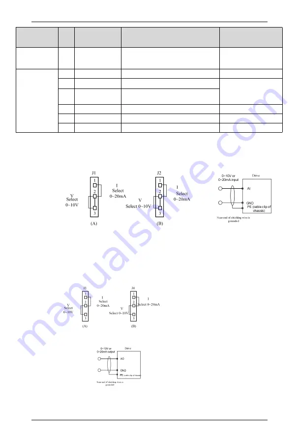
2.4.3 Wiring of analog input and output terminals
AI1 and AI2 terminals receive analog signal input and select input voltage (0
~
10V) or input
current (0
~
20mA) through jumpers J1 and J2. Terminal wiring mode is shown in Figure 2-18(a):
Figure 2-18(a) Analog Input Terminal Wiring
The analog outputs AO1 and AO2 can output both voltage and current, which can be selected
by jumpers J3 and J4. AO1 and AO2 are default to 0~10v voltage output, and the corresponding
output physical quantities are set by parameters F5.25 and F5.26.
Figure 2-18(b) Analog Output Terminal Wiring