Data Transfer from CAD Files | CAD import (option 42)
8
HEIDENHAIN | TNC 620 | Conversational Programming User's Manual | 10/2017
331
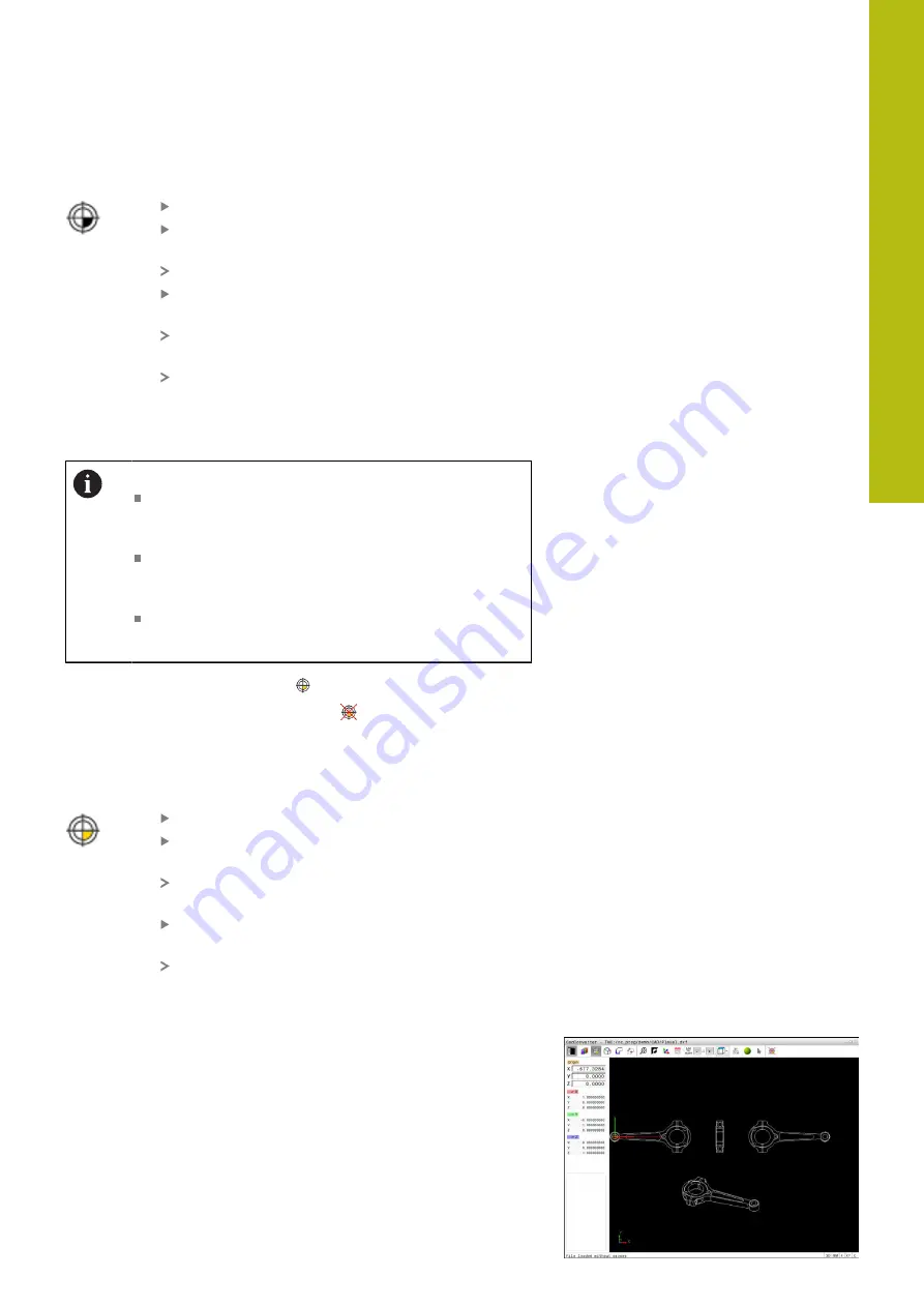
Selecting a preset on the intersection of two elements
Select the mode for specifying the preset
Click the first element (straight line, circle or
circular arc) with the left mouse button
The element is color-highlighted.
Click the second element (straight line, circle or
circular arc) with the left mouse button
The control sets the preset symbol on the
intersection.
You can adjust the orientation of the coordinate
system, if required.
of the coordinate system", page 331
Operating notes:
If there are several possible intersections, the control
selects the intersection nearest the mouse-click on
the second element.
If two elements do not intersect directly, the control
automatically calculates the intersection of their
extensions.
If the control cannot calculate an intersection, it
deselects the previously selected element.
If a preset is set, the color of the
"Setting a preset" icon changes.
You can delete a preset by pressing the
icon.
Adjusting the orientation of the coordinate system
The position of the coordinate system is defined by the orientation
of the axes.
The preset has already been set
Left-click an element that is in the positive X
direction
The control aligns the X axis and displays it in red
in the list view.
Left-click an element that is approximately in the
positive Y direction
The control aligns the Y and Z axes and displays
them in green and blue in the list view.
Element Information
In the Element Information window, the control shows how far the
preset you have chosen is located from the drawing datum, and
how this reference system is oriented with respect to the drawing.
Summary of Contents for TNC 620 E
Page 4: ......
Page 5: ...Fundamentals...
Page 34: ...Contents 34 HEIDENHAIN TNC 620 Conversational Programming User s Manual 10 2017...
Page 63: ...1 First Steps with the TNC 620...
Page 86: ......
Page 87: ...2 Introduction...
Page 123: ...3 Operating the Touchscreen...
Page 139: ...4 Fundamentals File Management...
Page 199: ...5 Programming Aids...
Page 228: ......
Page 229: ...6 Tools...
Page 271: ...7 Programming Contours...
Page 323: ...8 Data Transfer from CAD Files...
Page 344: ......
Page 345: ...9 Subprograms and Program Section Repeats...
Page 364: ......
Page 365: ...10 Programming Q Parameters...
Page 467: ...11 Miscellaneous Functions...
Page 489: ...12 Special Functions...
Page 532: ......
Page 533: ...13 Multiple Axis Machining...
Page 596: ......
Page 597: ...14 Pallet Management...
Page 610: ......
Page 611: ...15 Batch Process Manager...
Page 619: ...16 Manual Operation and Setup...
Page 693: ...17 Positioning with Manual Data Input...
Page 698: ......
Page 699: ...18 Test Run and Program Run...
Page 737: ...19 MOD Functions...
Page 774: ......
Page 775: ...20 Tables and Overviews...


