


IB -26
AIR CONDITIONING
O N VEHICLE SERVICE
EV A C U A TIN G A N D C H A R G IN G PROCEDURES
M ETA L TUBE
O UTSIDE
D IA M E T E R
T H R E A D AND
F IT T IN G SIZE
STEEL
T U B IN G
TO RQ UE
L B . F T .
N m
a l
D
m i n
O W S
r
COPPER
TU BING
TORQUE
LB. FT.
N m
N O M IN A L
TORQUE
W RENCH SPAN
1/4
7/16
10-15
14-20
6-7
7-9
5/8
3/8
5/8
30-35
41-48
11-13
15-16
3 /4
1/2
3/4
30-35
41-48
16-20
20-27
7/8
5/8
[ I -
30-36
4 1 4 8
21-27
29-37
1 1 /ie
....... 3/4
1 1/18
30-36
41-48
28-33
38-46
P R E C A U TIO N A R Y SERVICE MEASURES
Before any service is attem p te d which requires opening
of refrig eran t lines or com ponents, the person doing the
work should be thoroughly fam iliar with the inform ation
under P R E C A U T IO N S IN H A N D L IN G R e frig e ra n t-12,
P R E C A U T IO N S IN H A N D L IN G R E F R IG E R A N T
L IN E S A N D F IT T IN G S M A IN T A IN IN G C H E M IC A L
S T A B IL IT Y IN T H E R E F R IG E R A T IO N S Y S T E M ,
A N D R E F R IG E R A N T C H A R G IN G P R E C A U T IO N S
and should follow very c a re fu lly th e D IS C H A R G IN G ,
E V A C U A T IN G , O IL A D D IT IO N A N D C H A R G IN G
T H E R E F R IG E R A N T S Y S T E M instructions given on the
following pages for the unit being serviced.
Sealing caps should be removed from subassem blies
ju st prior to m aking connections for final assem bly. Use a
sm all am ount of clean 525 viscosity refrigerant oil on all
tube and hose joints. Always use new " O " rings dipped in
the clean 525 viscosity re frig eran t oil when assem bling
joints. T he oil will aid in assem bly and help provide a leak-
proof joint. W hen tightening joints, use a second wrench to
hold stationary part of connection so th a t a solid feel can be
attain ed . This will indicate proper assembly.
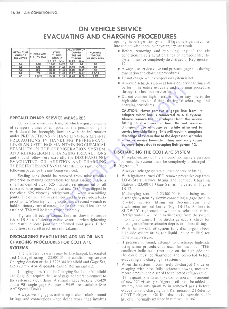
T ighten all tubing connections, as shown in torque
C h a rt 1B-8. Insufficient or excessive torque when tightening
can result in loose joints or deform ed joint parts. E ither
condition can result in refrig eran t leakage.
D IS C H A R G IN G E V A C U A T IN G A D D IN G OIL A N D
C H A R G IN G PROCEDURES FOR CCOT A / C
SYSTEMS
T he refrig eran t system m ay be D ischarged, Evacuated
and C h a rg e d using J -2 3 500-01 a ir cond itio n in g service
C harging S tatio n or the J-5725-04 M anifold and G age Set,
and 420 m l-14 oz. disposable cans of R efrig e ra n t-12.
C harging lines from the C harging S tation or M anifold
and G age Set require the use of gage adapters to connect to
the system service fittings. A stra ig h t gage A dapter J-5420
and a 90° angle gage A d ap ter J-9459 are available (See
A /C Special Tools).
Always w ear goggles and w rap a clean cloth around
fittings and connections w hen doing w ork th a t involves
opening the refrigeration system. If liquid refrig eran t comes
into contact with the skin or eyes injury can result.
• Before rem oving and replacing any of the air
conditioning refrig e ratio n lines or com ponents, the
system m ust be com pletely discharged of R egrigerant-
1 2
.
• Always use service valve and pressure gage sets during
evacuation and charging procedures.
• Do not charge while com pressor system is hot.
• Always discharge system at low-side service fitting and
perform the entire evacuate and charging procedure
through the low-side service fitting.
• Do not connect high pressure line or any line to the
high-side service fitting d u rin g d isch arg in g and
charging procedures.
C A U TIO N : N ever rem ove a g a g e line from its
a d a p te r w h e n line is connected to A /C system.
A lw a y s rem ove th e line a d a p te r from the service
fittin g to disconnect a lin e . Do not rem o ve
ch a rg in g hose a t g a g e set w h ile a tta c h e d to
service low -side fittin g . This w ill result in com plete
discharge of system d u e to th e depressed schrader
valve in service low -side fittin g a n d m a y cuase
personal injury d u e to escaping R e frig e ra n t-1 2.
D IS C H A R G IN G THE CCOT A / C SYSTEM
In replacing any of the air conditioning refrigeration
com ponents the system m ust be com pletely discharged of
R e frig e ra n t-12.
Always discharge system at low side service fitting.
1. W ith ignition turned O F F , remove protective cap from
L O W -S ID E service fitting and connect C h arg in g
Station J-2 3 500-01 G age Set as indicated in Figure
1 B-12.
If ch arg in g statio n J -2 3 500-01 is not being used,
discharge system by slowly connecting a gage hose to
low-side
service
fitting
on
A c c u m u la to r
and
discharging into oil bottle (Fig. I B - 12). As hose is
S L O W L Y tig h ten ed down onto sc h ra d e r valve,
R efrig e ra n t-12 will be in to discharge from the system
into the container. If no discharge occurs, check for
missing or defective schrader depressor in hose fitting.
2. W ith the low-side of system fully discharged, check
high-side system fitting (on liquid line or muffler) for
rem aining pressure.
3. If pressure is found, attem p t to discharge high-side
using sam e p rocedure as used for low-side. (T his
condition indicates a restriction on the high-side and
the cause m ust be diagnosed and co rre cted before
evacuating and charging the system ).
4. W hen the system is com pletely discharged (no vapor
escaping with hose fully-tightened down), m easure,
record am ount and discard the collected refrigerant oil.
If this q u antity is 15 ml (1 /2 oz.) or more, this am ount
of new 525 viscosity refrigerant oil m ust be added to
system , plus any q u a n tity in rem oved p a rts before
evacuation and charging with R e frig e ra n t-12 (R efer to
C C O T R efrigerant Oil D istribution for specific q u an
tity of oil norm ally retained in rem oved parts).
Summary of Contents for 1982 Light Duty Truck
Page 1: ......
Page 28: ...HEATER 1A 3 Fig lA 2 Heater Control C K Models Fig lA 3 Heater Control G Models...
Page 37: ...Fig 1A 11 T E E V A L V E A S M TEE AND VALVE C36...
Page 38: ...HEATER 1A 13 Fig 1A l2 Distributor Ducts G Models Fig 1A l5 Control Assembly G Models...
Page 39: ...1A 14 HEATER V IE W A V IE W B Fig 1A l7 Control Cable Routing G Models...
Page 42: ...HEATER 1A 19 Fig 1A 23 Auxiliary Heater Hose Routing...
Page 56: ...AIR CONDITIONING IB 13 Chart 1B 4 Pressure Cycling CCOT System Diagnosis...
Page 64: ...Fig 1B 17 C60 System Vacuum Diagram C K Series...
Page 65: ......
Page 66: ...Fig 1B 19 C60 Motor Home Chassis Wiring Diagram SWITCH AIR CONDITIONING IB 2 3...
Page 67: ...IB 24 AIR CONDITIONING Fig IB 20 1 P A C Harness Wiring...
Page 68: ...AIR CONDITIONING IB 25 VIE W A Fig IB 21 A C Compressor wiring...
Page 76: ...AIR CONDITIONING IB 33 Fig 1B 26 Compressor Mounting...
Page 91: ...IB 48 AIR CONDITIONING Fig 1B 59 C K Models Refrigerant Lines L6...
Page 150: ......
Page 162: ......
Page 164: ...2D 2 BODY Fig 2D 4 Typical Utility Vehicle Model...
Page 182: ...2D 20 BODY Fig 2D 51 Rear Door Controls Fig 2D 52 Rear Door Outside Handle and Lock Cylinder...
Page 193: ...BODY 2D 31 BELTS 3RD SEAT Fig 2D 82 Seat Belt Installation Suburban Driver Seat Suburban...
Page 194: ...2D 32 BODY Fig 2D 85 Passenger s Bucket Seat Chassis Cab...
Page 195: ...BODY 2D 33 Fig 2D 88 Rear Bench Seats Suburban...
Page 196: ...2D 34 BODY Fig 2D 89 CK Utility Seat Attachments...
Page 197: ...BODY 2D 35 Fig 2D 90 Seat Separator Compartment and Door CK Models...
Page 222: ......
Page 223: ...BODY 2D 61 Fig 2D 139 Front Seat Belt Installation...
Page 228: ......
Page 234: ......
Page 252: ...3B2 8 MANUAL STEERING GEAR Fig 3B2 11 Manual Steering Gear Exploded View...
Page 256: ......
Page 273: ...POWER STEERING SYSTEM 3B3 17 with LE3 Engine Exc HC4 LE4 LG9 LF4 LS9 LT9 and JB7 HC4 and JB8...
Page 342: ......
Page 389: ...REAR SUSPENSION 3D 7 Fig 3D 17 Rear Spring Installation C K Models...
Page 428: ...4 B 1 4 REAR AXLE Fig 4B 8 Gear Tooth Nomenclature Fig 4B 9 G ear Tooth Contact Pattern Check...
Page 444: ......
Page 454: ......
Page 468: ...4 B 5 2 REAR AXLE Fig 4B5 2 Rockwell Assembly...
Page 480: ...4 B 5 1 4 REAR AXLE...
Page 482: ...i...
Page 502: ......
Page 520: ......
Page 533: ...Fig 5 5 Front Brake Pipes and Hoses C K Models BRAKES 5 13...
Page 534: ...Fig 5 6 Front Brake Pipes and Hoses G M odels 5 14 B R A K E S...
Page 535: ...Fig 5 7 Front Brake Pipes and Hoses P Models BRAKES 5 15...
Page 536: ...5 16 BRAKES Fig 5 8 Rear Brake Hoses...
Page 538: ...5 18 BRAKES Fig 5 10 Parking Brake System Typical...
Page 539: ...BRAKES 5 19...
Page 570: ...5 50 BRAKES Fig 5 57 Power Steering Hose Routing C K Models...
Page 571: ...BRAKES 5 51 Fig 5 58 Power Steering Hose Routing G Models...
Page 572: ...Fig 5 59 Power Steering H ose Routing P Models 5 52 BRAKES...
Page 577: ...BRAKES 5 57 4 CONT A SECONDARY DIAPHRAGM B SECONDARY POWER 4 CONT C PRIMARY D Fig 5 5A Service...
Page 604: ......
Page 625: ...NOTES ENGINE 6 21...
Page 626: ......
Page 629: ...IN LINE 6 6A1 3 OIL PRESSURE SENDING UNIT Fig 6A1 1 In Line Engine Lubrication...
Page 630: ...6A1 4 IN LINE 6 Fig 6 A l 2 P Series Engine Front Mount...
Page 631: ...IN LINE 6 6A1 5 Fig 6Al 3 P Series Engine Rear Mount Fig 6 A l 4 C Series Engine Rear Mounts...
Page 634: ...6A1 8 IN LINE 6 Fig 6Al 7 K Series Engine Rear Mount...
Page 660: ......
Page 663: ...SMALL BLOCK 6A4 3 Fig 6A4 T Engine Lubrication...
Page 664: ...6A4 4 SMALL BLOCK Fig 6A4 2 Engine Lubrication...
Page 665: ...Fig 6A4 3 P Series Engine Mount Bracket...
Page 667: ...SMALL BLOCK 6A4 7 Fig 6A 4 5 P Series Engine Front Mount...
Page 668: ...6A4 8 SMALL BLOCK...
Page 669: ...SMALL BLOCK 6A4 9 Fig 6A 4 7 K Series Engine Mounts...
Page 670: ...6A4 10 SMALL BLOCK Fig 6A 4 8 C Series Engine Mounts...
Page 703: ...MARK IV 6A5 7 Fig 6A 5 6 P Series Engine Front Mount...
Page 704: ...6A5 8 MARK IV Fig 6 A 5 7 C Series Engine Mounts...
Page 731: ...6 2 DIESEL 6A7 3...
Page 760: ...6B 6 ENGINE COOLING Fig 6B 7 A C and A I R Adjustment...
Page 771: ...ENGINE COOLING 6B 17 Fig 6B 20 Engine O il C o o le r 6 2L Diesel...
Page 784: ......
Page 807: ...CARBURETOR MODEL 2SE 6C2 9 Fig 6C2 6 Typical 2SE Carburetor Assembly...
Page 820: ......
Page 830: ...6C4 10 CARBURETOR MODEL M4ME M4MC 101368 Fig 6C4 12 M 4M C M 4M E Carburetor Exploded View...
Page 848: ......
Page 876: ......
Page 888: ...6D 12 ENGINE ELECTRICAL Fig 6D 6C Generator Mounting Fig 6D 7C Generator Mounting...
Page 919: ...ENGINE ELECTRICAL 6D 43...
Page 934: ...Fig 6D 8E Starter M otor Mounting...
Page 974: ......
Page 1011: ...Figure 350C 25A Neutral Engine Running AUTOMATIC TRANSMISSION 350C 11...
Page 1054: ...Fig 7A 1C 400 Autom atic Transmission Side Cross Section Typical...
Page 1152: ...700 R4 40 AUTOMATIC TRANSMISSION Figure 700 R4 76 Transmission Assembly Exploded View...
Page 1162: ......
Page 1189: ...89MM MANUAL TRANSMISSION 7B3 5 Fig 7 3 4 4 Speed 89mm Exploded View...
Page 1219: ...CLUTCH 7C 5 Fig 7C 6 C K Truck Clutch Controls...
Page 1220: ...Fig 7C 7 G Truck Clutch Controls...
Page 1221: ...CLUTCH 7C 7 Fig 7C 8 P Truck Clutch Controls...
Page 1234: ...7E 2 TRANSFER CASE Fig 7E 1 Model 208 Transfer Case Cross Section...
Page 1252: ...7E 20 TRANSFER CASE Fig 7E 39 Transfer Case Attachment Typical...
Page 1278: ...8A 16 ELECTRICAL BODY AND CHASSIS Fig 8A 11 License Plate Lamps C K Series...
Page 1280: ...8A 18 ELECTRICAL BODY AND CHASSIS VIEW A VIEW B Fig 8A 15 CK Series Rear Lamp W iring...
Page 1281: ...ELECTRICAL BODY AND CHASSIS 8A 19 Fig 8A 16 CK Series Auxiliary W iring...
Page 1290: ...8B 8 ELECTRICAL AND WIRING Fig 8B 13 Seat Belt Reminder System Schematic...
Page 1292: ......
Page 1346: ...8C 54 INSTRUMENT PANEL AND GAGES Fig 8C 46 CK Series W iring 3 of 29...
Page 1351: ...INSTRUMENT PANEL AND GAGES 8C 59 SUBURBAN Fig 8C 51 CK Series W iring 8 of 29...
Page 1364: ...8C 72 INSTRUMENT PANEL AND GAGES Fig 8C 64 CK Series W iring 21 of 29...
Page 1365: ...INSTRUMENT PANEL AND GAGES 8C 73 CAB CRFW CAB CHASSIS Fig 8C 65 CK Series W iring 22 of 29...
Page 1366: ...8C 74 INSTRUMENT PANEL AND GAGES Fig 8C 66 CK Series W iring 23 of 29...
Page 1374: ...8C 82 INSTRUMENT PANEL AND GAGES Fig 8C 74 G Series W iring 2 of 19...
Page 1375: ...INSTRUMENT PANEL AND GAGES 8C 83 Fig 8C 75 G Series W iring 3 of 19...
Page 1376: ...8C 84 INSTRUMENT PANEL AND GAGES Fig 8C 76 G Series W iring 4 of 19...
Page 1379: ...INSTRUMENT PANEL AND GAGES 8C 87 Fig 8C 79 G Series W iring 7 of 19...
Page 1383: ...INSTRUMENT PANEL AND GAGES 8C 91 Fig 8C 83 G Series W iring 11 o f 19...
Page 1384: ...8C 92 INSTRUMENT PANEL AND GAGES BUS BARGWO Fig 8C 84 G Series W iring 12 of 19...
Page 1390: ...8C 98 INSTRUMENT PANEL AND GAGES Fig 8C 90 G Series W iring 18 of 19...
Page 1391: ...INSTRUMENT PANEL AND GAGES 8C 99 Fig 8C 91 G Series W iring 19 of 19...
Page 1392: ...8C 100 INSTRUMENT PANEL AND GAGES Fig 8C 92 P Series W iring 1 of 11...
Page 1393: ...INSTRUMENT PANEL AND GAGES 8C 101 Fig 8C 93 P Series W iring 2 of 11...
Page 1396: ...8C 104 INSTRUMENT PANEL AND GAGES Fig 8C 96 P Series W iring 5 of 11...
Page 1399: ...INSTRUMENT PANEL AND GAGES 8C 107 Fig 8C 99 P Series W iring 8 of 11...
Page 1401: ...INSTRUMENT PANEL AND GAGES 8C 109 START RUN OF LOCK ACC Fig 8C 101 P Series W iring 10 of 11...
Page 1415: ...ACCESSORIES 9 13 RADIO NOISE BLOWER MOTOR Fig 9 6R Radio Diagnosis Chart B...
Page 1416: ...9 14 ACCESSORIES D E A D R A D IO A M R A D IO I Fig 9 7R Radio Diagnosis Chart C...
Page 1417: ...ACCESSORIES 9 15 DEAD RADIO AM FM RADIO Fig 9 8R Radio Diagnosis Chart D...
Page 1435: ...t f l i t 1...


