Operation
CG-1220 DTR
4-7
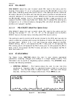
SPU SERIAL LINK STATS
–
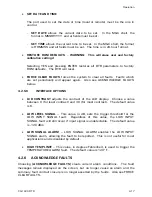
This screen displays SPU RS422 serial link
statistics separately for the MCU and DSP. Timeouts are displayed when
the CPU did not get a response within 100ms. Errors are logged when an
unexpected response did not match internal protocol. The percentage of
errors plus timeouts versus the total number of commands is displayed.
Linklosses displays the number of failures to establish communication with
the MCU or DSP processors. Finally, the total number of commands sent is
displayed.
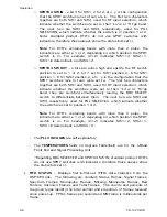
I/O STATUS –
Current I/O status information obtained from the I/O card is
displayed. This information is intended for diagnostic purposes. Given data
format x(y), all x are hex and all y are human-interpretable synonyms of x. x
is the internal configuration value useful to GDST technical support (it is
subject to change without notice). y is loosely the selected band, but more
specifically: (-) if x is undefined (more than one or none), ( ) if x is none; see
the specific field description for more details.
-
The
INTF#1
and the
INTF#2
fields provide information regarding the input
and output states of the I/O INTERFACE #1 and I/O INTERFACE #2
connectors on the back panel.
-
FAULTS
is a 4-bit mask where bit 0 is the fault indicator of the first BDC,
bit 1 is of the second, etc. A zero bit means the BDC is present and
powered off (or malfunctioning). "ok" or "BAD" is display, the latter if
the BDC for the current band is malfunctioning or not powered up.
-
The
BDC
fields are internal bit settings that the I/O card uses to set the
correct BDC for the selected band.
o
BDC POWER IN
- y is the number of the BDC whose power is on.
o
BDC SELECTED
- x bits are active low (e.g. 0x7=~0x8,... 0xE=~1).
y is the number of the BDC whose RF output is selected. Note:
standard product DTR's do not use SPDT switches with indicators,
therefore these always show the status bits set (-).
o
BDC POWER OUT
- x bits are active high and specify the BDC to turn
on and the others to turn off, bit 7 for BDC 1 on, bit 6 for BDC 1 off,
5 for BDC 2 on, etc. y is the number of the BDC whose power was
turned on.
o
BDC SELECT
- x bits are active high, bit 3 set for position 1, 2 for 2,
etc. y is the number of the BDC whose RF output was selected.
-
The
SPDTX4
fields are internal bit settings that the I/O card uses to set
the correct RF switch settings.
Summary of Contents for CG-1220
Page 6: ...vi THIS PAGE INTENTIONALLY LEFT BLANK...
Page 10: ...Table of Contents x THIS PAGE INTENTIONALLY LEFT BLANK...
Page 16: ......
Page 54: ...Maintenance 5 4 CG 1220 DTR THIS PAGE INTENTIONALLY LEFT BLANK...
Page 56: ...Engineering Drawings 6 2 CG 1220 DTR THIS PAGE INTENTIONALLY LEFT BLANK...
Page 65: ...Appendix C DTR Remote M C Protocol CG 6073 Rev R Jun 2012 4 THIS PAGE INTENTIONALLY LEFT BLANK...
Page 130: ...Remote M C Protocol C 2 CG 1220 DTR THIS PAGE INTENTIONALLY LEFT BLANK...
Page 134: ...Acronyms Abbreviations D 4 CG 1220 DTR THIS PAGE INTENTIONALLY LEFT BLANK...


