Operation
4-14
CG-1220 DTR
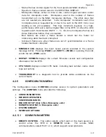
LOW FREQUENCY
is the low
-
end frequency of the down-conversion device
that supports this band. Factory default is the low-end frequency of the
internal BDC. If utilizing an external down-conversion device, it should be
that device’s low-end frequency.
HIGH
FREQUENCY
is the high-end frequency of the down-conversion device
that supports this band. Factory default is the high-end frequency of the
internal BDC. If utilizing an external down-conversion device, it should be
that device’s high-end frequency.
LBAND-DEFAULTS
sets BAND 1 parameters to L-Band defaults.
WARNING:
Changing these values for units with internal BDC may cause the DTR to stop
working. Only change these values when an internal BDC is present in the unit when directed to do
so by GDST customer support personnel.
4.2.5.4
BEACON SETUP*
* Only available in Non-Monopulse units.
A subset of DTR system parameters may be stored as BEACONS to provide parallel
control via I/O Interface #1. This provides support of legacy GDST interfaces,
such as the 7134 ACU. See Section 3.5.2 for more information on setting up
beacons with a 7134 ACU.
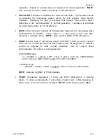
STORE BEACONS
– Executing each item in this menu will store current
values of the following parameters as a BEACON state:
FREQUENCY
SLOPE
POL-SELECT
VOLTAGE RANGE
ATTENUATION
MINIMUM POWER REFERENCE
FILTER
LEVEL
INPUT ATTEN
Only DAC1 SLOPE, VOLTAGE RANGE, and MINIMUM POWER REFERENCE
LEVEL are stored. Those parameters for DAC2 are not stored.
RESTORE BEACONS
– Executing each item in this menu will restore values
previously stored as a BEACON state.
4.2.5.5 MONOPULSE*
* Only available in Monopulse units.
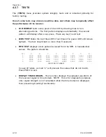
This MONOPULSE menu provides the ability to configure some aspects of
monopulse mode and view others. Monopulse mode uses one of the serial ports to
communicate with the GDST 7200 series ACU via the M&C SHELL. Control and
status of the monopulse RF signal processing assembly is provided via lines located
on the general purpose I/O interfaces.
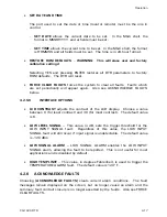
MUTE
controls the combination of signal and error channels in the
monopulse hardware. Disable to include the error channel for monopulse
Summary of Contents for CG-1220
Page 6: ...vi THIS PAGE INTENTIONALLY LEFT BLANK...
Page 10: ...Table of Contents x THIS PAGE INTENTIONALLY LEFT BLANK...
Page 16: ......
Page 54: ...Maintenance 5 4 CG 1220 DTR THIS PAGE INTENTIONALLY LEFT BLANK...
Page 56: ...Engineering Drawings 6 2 CG 1220 DTR THIS PAGE INTENTIONALLY LEFT BLANK...
Page 65: ...Appendix C DTR Remote M C Protocol CG 6073 Rev R Jun 2012 4 THIS PAGE INTENTIONALLY LEFT BLANK...
Page 130: ...Remote M C Protocol C 2 CG 1220 DTR THIS PAGE INTENTIONALLY LEFT BLANK...
Page 134: ...Acronyms Abbreviations D 4 CG 1220 DTR THIS PAGE INTENTIONALLY LEFT BLANK...


