Operation
CG-1220 DTR
4-1
4.0
OPERATION
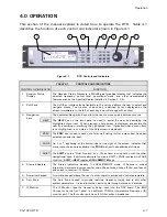
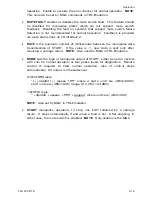
This section of the manual explains in detail how to operate the DTR. Table 4-1
describes the function of each control and indicator shown in Figure 4-1.
1
3
2
4
5
6
7
Figure 4-1
DTR Controls and Indicators
TABLE 4-1
CONTROLS AND INDICATORS
CONTROL OR INDICATOR
FUNCTION
1. Receiver
Status
Display
The Receiver Status Display is a 240x64-pixel graphical display that indicates the
selected frequency, power level, operational mode, and other user-selectable
features such as the Spectral Display (detailed in Section 4.2.4).
2. Soft Keys
The Soft-Key interface lends flexibility to the unit and allows the user to select and
navigate menus. The function of each key is defined by text displayed on the
screen immediately to the left of each key and will change with context.
The dedicated Navigation Keys allow the user to move quickly between menus.
HELP
The
HELP
key on the front panel is used to assist the user by describing the
highlighted menu item. When pressed, a help screen is displayed and assists the
user by describing or clarifying the highlighted item. If pressed when a menu item
is not highlighted, a summary of the help screen is displayed.
PREV
The
PREV
key is used to back out of menus. Pushing it after a menu item has been
selected cancels the input.
PAGE
An
or
, appearing at the bottom-right or top-right of the screen, indicates that
more menu choices are available. Use
PAGE
to show these additional choices.
SHIFT
3. Navigation
Keys
The
SHIFT
key is a “Dual Function” key. When used in conjunction with the other
navigational keys, it performs alternate functions. SHIFT+PAGE reverses the PAGE
function.
SHIFT+HELP
toggles
LOCAL
/
REMOTE
Mode.
4. Status
Indicators
The Status Indicators indicate 1) LOCAL/REMOTE mode; 2) Failure in critical
internal sub-systems (downconverter chain Phase-Locked Loops (PLLs) and loss of
phase lock in receiver); 3) Power.
5. Numerical Keypad
A numeric keypad allows the user to enter numeric entries and control parameters.
6. Spin Knob
The Spin Knob is used to provide real-time frequency tuning and to edit other
system parameters. It also allows the user to cycle through menus and choices.
7. IF Monitor
The IF Monitor taps the frequency being input into the DSP board. The BNC
Connector on the front panel is a buffered 70 MHz Intermediate Frequency (IF)
monitor port. The IF monitor port has a 50-Ohm output impedance.
Summary of Contents for CG-1220
Page 6: ...vi THIS PAGE INTENTIONALLY LEFT BLANK...
Page 10: ...Table of Contents x THIS PAGE INTENTIONALLY LEFT BLANK...
Page 16: ......
Page 54: ...Maintenance 5 4 CG 1220 DTR THIS PAGE INTENTIONALLY LEFT BLANK...
Page 56: ...Engineering Drawings 6 2 CG 1220 DTR THIS PAGE INTENTIONALLY LEFT BLANK...
Page 65: ...Appendix C DTR Remote M C Protocol CG 6073 Rev R Jun 2012 4 THIS PAGE INTENTIONALLY LEFT BLANK...
Page 130: ...Remote M C Protocol C 2 CG 1220 DTR THIS PAGE INTENTIONALLY LEFT BLANK...
Page 134: ...Acronyms Abbreviations D 4 CG 1220 DTR THIS PAGE INTENTIONALLY LEFT BLANK...

