Operation
4-8
CG-1220 DTR
o
SPDTX4 SW IN
- x bit 3 for SW1, 2 for 2, etc. y is the configuration
that the SPDT switches (one to four) are in. The first two characters
together are both SW1 and SW2, used for RF input selection, which
indicate whether the switches are set to their "Lo"w or "Hi"gh band.
The next two are SW3 and SW4, respectively, used for POL
SELECTION, which indicate whether the switch is in position 1 or 2.
Note: standard product DTR's do not use SPDT switches with
indicators, therefore these always show the status bits set (-).
Note
: For DTR’s containing bands with more than 2 poles, the
indicators are either a 1 or 2, depending on which position the SPDT
switch is in. For example, (21-2) indicates SW1=2, SW2=1,
SW3=in determinant, and SW4=2.
o
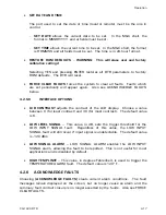
SPDTX4 SW OUT
- x bits are active high and specify the RF switch
position to set to 1 or 2, bit 7 set for SW1 position 2, 6 for SW1
position 1, 5 for SW2 position 2, etc. y is the configuration that the
SPDT switches (one to four) were set to. The first two characters
together are both SW1 and SW2, used for RF input selection, which
indicate whether the switches were set to their "Lo"w or "Hi"gh
band; they are switched simultaneously leaving the BDC SELECT
switch to differentiate between them. The next two are SW3 and
SW4, respectively, used for POL SELECTion, which indicate whether
the switch was set to position 1 or 2.
Note
: For DTR’s containing bands with more than 2 poles, the
indicators are either a 1 or 2, depending on which position the SPDT
switch is in. For example, (21-2) indicates SW1=2, SW2=1,
SW3=in determinant, and SW4=2.
-
The
PLL VOLTAGES
are self-explanatory.
-
The
TEMPERATURES
fields (in degrees Fahrenheit) are for the L-Band
Front End and Signal Processing Unit.
*Regarding BDC SELECTED and SPDTX4 SW IN, standard product DTR's
do not use SPDT switches with indicators, therefore these always show
the status bits set (-).
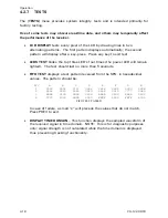
FIFO STATUS –
Displays first-in-first-out (FIFO) data statistics from the
DSP/CPU link. The following are counted: Status Frames, Signal Frames,
Spectrum Frames, Monopulse Frames, Missing Monopulse Frames, Bad
Footers, Unknown Frames and Total Frames. The counts and percents of
the given types identify the total number and proportion of frames received
since power-up. FPS is frames per second and MS/Frame is milliseconds per
frame.
Summary of Contents for CG-1220
Page 6: ...vi THIS PAGE INTENTIONALLY LEFT BLANK...
Page 10: ...Table of Contents x THIS PAGE INTENTIONALLY LEFT BLANK...
Page 16: ......
Page 54: ...Maintenance 5 4 CG 1220 DTR THIS PAGE INTENTIONALLY LEFT BLANK...
Page 56: ...Engineering Drawings 6 2 CG 1220 DTR THIS PAGE INTENTIONALLY LEFT BLANK...
Page 65: ...Appendix C DTR Remote M C Protocol CG 6073 Rev R Jun 2012 4 THIS PAGE INTENTIONALLY LEFT BLANK...
Page 130: ...Remote M C Protocol C 2 CG 1220 DTR THIS PAGE INTENTIONALLY LEFT BLANK...
Page 134: ...Acronyms Abbreviations D 4 CG 1220 DTR THIS PAGE INTENTIONALLY LEFT BLANK...


