Installation
3.0
INSTALLATION AND INITIAL SETUP
3.1 Introduction
This section provides the information necessary for the installation and initial setup
of the DTR.
3.2 Mechanical Installation
Using four #10 screws, mount the DTR in a standard 19-inch Electronic Industries
Association (EIA) equipment rack. Rear support and/or rack slides are not usually
necessary; however, rack slides may prove helpful during maintenance operations
and are available as an option.
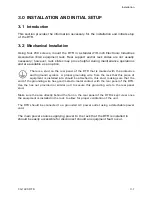
There is a stud on the rear panel of the DTR that is marked with the protective
earth (ground) symbol. A proper grounding wire from the rack that this piece of
equipment is installed into should be attached to this stud, making sure that the
end of the grounding wire has good metal-to-metal contact with the rear panel of the DTR.
Use the hex nut provided (or similar nut) to secure this grounding wire to the rear panel
stud.
Make sure the area directly behind the fan on the rear panel of the DTR is kept clear once
the equipment is installed in the rack to allow for proper ventilation of the unit.
The DTR should be connected to a grounded AC power outlet using a detachable power
cord.
The main power source supplying power to the rack that the DTR is installed in
should be easily accessible for disconnect should an equipment fault occur.
CG-1220 DTR
3-1
Summary of Contents for CG-1220
Page 6: ...vi THIS PAGE INTENTIONALLY LEFT BLANK...
Page 10: ...Table of Contents x THIS PAGE INTENTIONALLY LEFT BLANK...
Page 16: ......
Page 54: ...Maintenance 5 4 CG 1220 DTR THIS PAGE INTENTIONALLY LEFT BLANK...
Page 56: ...Engineering Drawings 6 2 CG 1220 DTR THIS PAGE INTENTIONALLY LEFT BLANK...
Page 65: ...Appendix C DTR Remote M C Protocol CG 6073 Rev R Jun 2012 4 THIS PAGE INTENTIONALLY LEFT BLANK...
Page 130: ...Remote M C Protocol C 2 CG 1220 DTR THIS PAGE INTENTIONALLY LEFT BLANK...
Page 134: ...Acronyms Abbreviations D 4 CG 1220 DTR THIS PAGE INTENTIONALLY LEFT BLANK...


