Operation
4-2
CG-1220 DTR
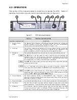
The
Receiver Status Display
, shown below in Figure 4-2, displays the frequency,
signal source and levels, faults, etc. along with the
Main Menu
of the DTR. Table
4-2 describes each display feature.
Figure 4-2
Receiver Status Display Screen
TABLE 4-2
RECEIVER STATUS DISPLAY
CONTROL OR INDICATOR
FUNCTION
1. Power Meter
Graphical representation of input signal level in dBm. Range automatically
adjusts relative to power level.
2. Signal Level
Input Signal level in dBm
3. Frequency
Frequency of the receiver in MHz
4. Carrier to Noise Ratio
Calculated C/No of tracking signal
5. Voltage
Output
Current analog voltage output
6. Fault Display
Displays faults and alarm conditions
7. Menu
Used to support the various system interfaces and control system
parameters.
Summary of Contents for CG-1220
Page 6: ...vi THIS PAGE INTENTIONALLY LEFT BLANK...
Page 10: ...Table of Contents x THIS PAGE INTENTIONALLY LEFT BLANK...
Page 16: ......
Page 54: ...Maintenance 5 4 CG 1220 DTR THIS PAGE INTENTIONALLY LEFT BLANK...
Page 56: ...Engineering Drawings 6 2 CG 1220 DTR THIS PAGE INTENTIONALLY LEFT BLANK...
Page 65: ...Appendix C DTR Remote M C Protocol CG 6073 Rev R Jun 2012 4 THIS PAGE INTENTIONALLY LEFT BLANK...
Page 130: ...Remote M C Protocol C 2 CG 1220 DTR THIS PAGE INTENTIONALLY LEFT BLANK...
Page 134: ...Acronyms Abbreviations D 4 CG 1220 DTR THIS PAGE INTENTIONALLY LEFT BLANK...


