Installation
3.3 Input and Output Connections
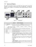
Refer to Figure 3-1 for a diagram showing the possible Input/Output (I/O)
connections to the DTR. Table 3-1 provides brief descriptions of each connection
or group of connections.
Figure 3-1
L-Band DTR-I/O Connections
NOTE: ACU I/O connections shown for reference only. The DTR may
be interfaced with any ACU having contact closures for beacon
selection and a tracking voltage input or a serial link utilizing the DTR’s
M&C command set.
3-2
CG-1220 DTR
Summary of Contents for CG-1220
Page 6: ...vi THIS PAGE INTENTIONALLY LEFT BLANK...
Page 10: ...Table of Contents x THIS PAGE INTENTIONALLY LEFT BLANK...
Page 16: ......
Page 54: ...Maintenance 5 4 CG 1220 DTR THIS PAGE INTENTIONALLY LEFT BLANK...
Page 56: ...Engineering Drawings 6 2 CG 1220 DTR THIS PAGE INTENTIONALLY LEFT BLANK...
Page 65: ...Appendix C DTR Remote M C Protocol CG 6073 Rev R Jun 2012 4 THIS PAGE INTENTIONALLY LEFT BLANK...
Page 130: ...Remote M C Protocol C 2 CG 1220 DTR THIS PAGE INTENTIONALLY LEFT BLANK...
Page 134: ...Acronyms Abbreviations D 4 CG 1220 DTR THIS PAGE INTENTIONALLY LEFT BLANK...


