background image

Appendix C– DTR Remote M&C Protocol 

CG-6073 (Rev R, June, 2012) 

3.0 GENERAL PROTOCOL 


The general format for transactions being sent to and from the DTR M&C interface 
is described below. 
 
Format for sending a command is: 
 

command [arguments]<CR> 

 
Format for information returned is: 
 

[data)] [(newline)(data)] ... [[(newline)] 
(error message)]prompt 

 
1. 

command - May be a Keyword, or menu item name or number.  Items are 
numbered 0 to n-1, where n is the number of items in the menu.  Note that 
some menu items may not be available depending on system configuration. 

 
2. 

[arguments] - 0 or more space-separated fields which are actually arguments 
to the command.  These are command-specific. 

 
3. 

<CR> - ASCII carriage return (ASCII 13 decimal).  Note that the DTR M&C 
expects only a carriage return; line feeds are not permitted. 

 
4. 

(newline) - User-definable: either CR (ASCII 13 decimal) or CRLF: (ASCII 13 
and ADCII10 decimal).  If a command returns data as part of its action, then 
each line of data is preceded by a (newline), except for the first line. 

 
6. 

(error message) -  Error message from the preceding command.  Depending 
on error status and user-definable options, there may or may not be an error 
message.  Most error messages are preceded with a (newline) as defined 
previously.  Error messages are described in Section 3.2. 

 
Argument fields sent to the M&C shell must always be separated by at least one 
space (ASCII 32 decimal). 
 
The command and all (if any) arguments are individual fields.  Note that more than 
one command may be issued on the same command line, as long as the maximum 
input length of 80 characters is not exceeded; however, output from those 
commands may be on the same line. 

Summary of Contents for CG-1220

Page 1: ...persons or the transmission of its contents outside the United States must be in compliance with U S Export Laws and Regulations The bearer of this document is under obligation to know the applicable...

Page 2: ...anner C Bolton 10 13 08 8195 L Amended Detection Description A Weaver D Weis 7 1 08 8008 K I O Status updated M Neely G Branch 4 25 06 6629 J Freq expanded to 945 2055 M Neely G Branch 2 06 06 6456 H...

Page 3: ...ROUNDING STICKS AND SHORT OUT HIGH VOLTAGE POINTS BEFORE SERVICING NEVER MAKE INTERNAL ADJUSTMENTS OR PERFORM MAINTENANCE OR SERVICE WHEN ALONE OR FATIGUED The manufacturer is specifically not liable...

Page 4: ...g directives R TTE Directive and its amending directives It has been designed and manufactured to the following specifications IEC 61010 1 1990 A1 1992 A2 1995 EN 300339 1998 EN 55022 1998 Class B EN...

Page 5: ...nts of its front and rear panels Section 2 0 Theory explains the theory of operation of the DTR Section 3 0 Installation outlines installation pin outs setup and initial power up of the DTR Section 4...

Page 6: ...vi THIS PAGE INTENTIONALLY LEFT BLANK...

Page 7: ...put Voltage Pin Out 3 3 1 1 2 3 4 Summary Fault Output 3 3 1 1 3 3 5 Beacon Select Inputs GPIO 0 3 3 3 1 1 4 3 6 General Purpose I O 3 3 1 1 5 3 6 External Pol Select Control Lines GPIO 6 7 4 5 8 9 3...

Page 8: ...CON SETUP 4 2 5 5 4 14 MONOPULSE 4 2 5 6 4 16 SYSTEM MEMORY 4 2 5 6 4 17 INTERFACE OPTIONS 4 2 6 4 17 ACKNOWLEDGE FAULTS 4 2 7 4 18 TESTS 5 0 5 1 MAINTENANCE 5 1 5 1 Inspection and Preventive Maintena...

Page 9: ...DEBAND CONFIG TABLE 3 3 3 4 I O INTERFACE 2 STANDARD WIDEBAND CONFIG TABLE 3 4 3 7 I O INTERFACE 1 MONOPULSE CONFIG TABLE 3 5 3 7 I O INTERFACE 2 MONOPULSE CONFIG TABLE 3 6 3 9 DEFAULT SERIAL INTERFAC...

Page 10: ...Table of Contents x THIS PAGE INTENTIONALLY LEFT BLANK...

Page 11: ...rward manner The unit s versatile settings allow the unit to interface with a wide range of next level system components 1 1 1 Explanation of Safety Symbols Symbol Explanation Protective Earth Ground...

Page 12: ...lues Dedicated online Help key Remote control capability RS 232 RS 422 RS 485 contact closures Front panel 70 MHz monitor port 50 BNC female Real time spectral display of tracking signal Field upgrade...

Page 13: ...DTR front panel is shown in Figure 1 1 with its controls and indicators identified The function of each is detailed in Section 4 Operation 1 3 2 4 5 6 7 Figure 1 1 DTR Front Panel TABLE 1 1 CONTROLS...

Page 14: ...ol and status 3 RS 232 A standard RS 232 serial port 4 RS 422 A standard RS 422 serial port Also configurable as an RS 232 serial port 5 RS 485 A standard RS 485 serial port 6 Power Supply Universal p...

Page 15: ...Zeros are entered for ranges not used TABLE 1 4 Frequency Range Chart for DTR Digit Band Include Pol Select Switch Freq Range BDC P N 0 None 1 No 2 L Band Yes 0 945 2 055 GHz None 3 No 4 S Band Yes 2...

Page 16: ......

Page 17: ...Transform FFT and analyzes the band for signal and noise content The signal power and signal to noise information is estimated and the values are sent to the System Control Processor SCP The SCP sets...

Page 18: ...g or switching 2 2 2 Down Converter Frequencies RF signals enter the DTR on one of six possible inputs and are routed to the proper Block Down Converter BDC for conversion to an L band signal of 950 M...

Page 19: ...ol A proper grounding wire from the rack that this piece of equipment is installed into should be attached to this stud making sure that the end of the grounding wire has good metal to metal contact w...

Page 20: ...3 1 provides brief descriptions of each connection or group of connections Figure 3 1 L Band DTR I O Connections NOTE ACU I O connections shown for reference only The DTR may be interfaced with any A...

Page 21: ...losure Additionally there are several general purpose inputs and outputs that can be used to change the receiver s operational mode See Tables 3 2 and 3 3 for pin outs SERIAL INTERFACE 1 This serial p...

Page 22: ...2 SHLD_OUT Shield for OUT pair 3 16 AUX AUX DAC 2 Analog Output Voltage 2 Common 15 SHLD_AUX Shield for AUX pair 4 17 SUM_FLT Summary fault relay contacts 5 18 GPIO 8 Command Return POL 5 Select Cont...

Page 23: ...nlocked Temperature alarm NVRAM corrupted Mute Switch Fault SPU Link locked 3 3 1 1 3 Beacon Select Inputs GPIO 0 3 The BEACON SELECT inputs not available on Monopulse units are formed through pin gro...

Page 24: ...control lines on the GPIO 6 and 7 of I O Interface 1 This was implemented for backward compatibility with a GDST Model TRL Tracking Receiver which provided some I O lines to facilitate control of an e...

Page 25: ...mand Return Frequency Band Control Optional 11 24 GPIO 6 Command Return POL 1 select control line 12 25 GPIO 7 Command Return POL 2 select control line 13 SIG_GND Reserved signal DTR signal ground THI...

Page 26: ...he monopulse error channel while allowing the sum channel to pass Mute is normally on when the DTR is commanded to start monopulse mute is turned off It can be set in the MONOPULSE menu 3 3 1 2 3 Mute...

Page 27: ...pin outs coexist on the same 9 pin connector without conflict Both serial ports are 9 pin D subminiature socket connectors Pin outs for the Serial Interface Ports 1 and 2 are given in Tables 3 7 and 3...

Page 28: ...figs Comm Parameters Port 3 8 Data bits No parity These parameters cannot be changed by the user 1 stop bit Port 3 is a half duplex RS 485 port and is a 9 pin D subminiature socket connector Pin outs...

Page 29: ...the following steps 1 Set the DTR rear panel POWER switch to ON 2 Verify that the 240x64 pixel graphical receiver status display shows a normal operational mode A default frequency and signal acquisit...

Page 30: ...F POWER LEVEL to obtain 8 VDC Note If both DAC1 and DAC2 are enabled the front panel display will report DAC1 voltage real time not at specified DAC1 update rate If DAC1 is disabled and DAC2 is enable...

Page 31: ...Port 3 is RS 485 only and cannot be used with a 7200 ACU TABLE 3 11 DTR TO 7200 ACU SERIAL CONNECTIONS MATRIX 7200 ACU PORT J14 1 J15 2 J16 3 J17 4 J18 5 J19 6 J20 7 1 RS232 RS232 X X X X X 2 RS232 R...

Page 32: ...0 max 57600 Echo Disabled Newline CR only Shell M C Shell 8 data No parity 1 stop bit are factory set cannot be changed ACU Port 1 7 BPS 19200 max is 38400 Parity None Data Bits 8 Stop Bits 1 Shell DT...

Page 33: ...ed item If pressed when a menu item is not highlighted a summary of the help screen is displayed PREV The PREV key is used to back out of menus Pushing it after a menu item has been selected cancels t...

Page 34: ...ISPLAY CONTROL OR INDICATOR FUNCTION 1 Power Meter Graphical representation of input signal level in dBm Range automatically adjusts relative to power level 2 Signal Level Input Signal level in dBm 3...

Page 35: ...ough menus items with the Spin Knob Once the desired menu is highlighted press the ENTER key 4 1 2 What Happens When a Menu is Selected Selecting a menu does one of three things depending on its conte...

Page 36: ...ration 4 4 CG 1220 DTR 4 1 2 3 Executes an Action A menu such as ACKNOWLEDGE FAULTS does not have submenus and does not open an editor Instead it performs an action and maintains the current menu scre...

Page 37: ...e spin knob When the receiver is in REMOTE control controlled by the data link that is configured as the port in control frequency editing is initiated and executed using ASCII M C commands via the da...

Page 38: ...the main menu indicating which POL input is active This setting is used to control an RF switch internal to the DTR and may also be used to control an external switch using I O Interface 1 and or I O...

Page 39: ...lds provide information regarding the input and output states of the I O INTERFACE 1 and I O INTERFACE 2 connectors on the back panel FAULTS is a 4 bit mask where bit 0 is the fault indicator of the f...

Page 40: ...r RF input selection which indicate whether the switches were set to their Lo w or Hi gh band they are switched simultaneously leaving the BDC SELECT switch to differentiate between them The next two...

Page 41: ...n frames are when frames are out of synchronization or a frame header has been corrupted MESSAGE LOG displays the most recent events recorded in the system message buffer Pressing PAGE and SHIFT PAGE...

Page 42: ...remote port set to DTR and a DTR set to 72xx M C SHELL will NOT communicate MESSAGE PRINTER is a diagnostic tool which may be used to record system events when connected to a terminal program or a ser...

Page 43: ...frequency A signal is detectable if it is visible on the spectral display MAIN STATUS SPECTRAL DISPLAY A spectrum analyzer attached to the IF Monitor port may be used to view the filter band Filters 1...

Page 44: ...M REFERENCE POWER LEVEL and SLOPE may be independently set up However the UPDATE RATE applies to both DAC outputs ATTENUATION controls the lower end of the Digital to Analog Converter DAC voltage outp...

Page 45: ...the actual beacon frequency to be entered as the tracking frequency rather than the down converted L Band frequency being entered as the tracking frequency For example if an L Band DTR is being used t...

Page 46: ...trol via I O Interface 1 This provides support of legacy GDST interfaces such as the 7134 ACU See Section 3 5 2 for more information on setting up beacons with a 7134 ACU STORE BEACONS Executing each...

Page 47: ...1 new data is sent only after receiving a carriage return NOTE Also used by M C in TRL Emulation MODE sets the type of monopulse output of START either two error vectors with sum for normal operation...

Page 48: ...7 Record and enter the measured value 4 Peak search the signal NCO OFFSET adjusts the frequency of the Numerically Controlled Oscillator NCO on the SPU POWER LEVEL CALIBRATION adjusts the calibration...

Page 49: ...LCD CONTRAST adjusts the contrast of the LCD display Choose a value between 0 for least contrast and 30 for most contrast The default value is 6 LOW LEVEL SIGNAL This value in dB sets the trigger thr...

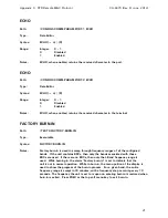
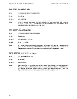
Page 50: ...ill remain lighted The test should last no more than 5 seconds FIFO TEST displays a test pattern received from the SPU in hexadecimal values The pattern should be R C A B C D E F G H 1 0000 0001 1111...

Page 51: ...e the fan housing by re installing the 4 screws washers and nuts Replace batteries for non volatile memory as required The long life battery ensures that user parameters are stored when the unit is po...

Page 52: ...y acquire the GDST part BBA003 Panasonic CR2354 This 3V Lithium coin type battery can be carefully pried out with a small screwdriver and the new battery can be replaced in reverse fashion IMPORTANT T...

Page 53: ...arts can be ordered from General Dynamics SATCOM Technologies TABLE 5 1 SPARE PARTS P N DESCRIPTION QTY PER SYS CFU079 Fuse 1 Amp fuse 1 CSS091 Filter power entry module 85 265 VAC 1 BBA003 Battery co...

Page 54: ...Maintenance 5 4 CG 1220 DTR THIS PAGE INTENTIONALLY LEFT BLANK...

Page 55: ...Engineering Drawings 6 0 ENGINEERING DRAWINGS This section of the manual contains the following engineering drawing 201807 Digital Tracking Receiver Stock Level Drawing CG 1220 DTR 6 1...

Page 56: ...Engineering Drawings 6 2 CG 1220 DTR THIS PAGE INTENTIONALLY LEFT BLANK...

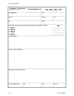
Page 57: ...PLAY VERSION and have the DTR s Model Serial and corresponding software versions readily available If the unit will not function please consult the Model Serial tag on the side of the unit for the pro...

Page 58: ...T FAX EMAIL EQUIPMENT INCLUDE MODEL NAME AND SERIAL NUMBER OF ALL PERTINENT EQUIPMENT 1 Model 2 Model 3 Model 4 Model S N _________________ _________________ _________________ _________________ OTHER...

Page 59: ...Menu Tree APPENDIX B MENU TREE This Appendix contains the menu tree for the DTR CG 1220 DTR B 1...

Page 60: ...ILABLE WITH OPTIONAL BDCs BAND 1 BAND 3 BAND 2 BAND 4 BDC GAIN HIGH FREQ LBAND DEFAULTS OSC FREQ LOW FREQ BAND 1 ONLY 3 RESTORE ROM DEFAULTS 4 FORCE CLEAR FAULTS 6 INTERFACE OPTIONS 1 LCD CONTRAST 2 L...

Page 61: ...Remote M C Protocol APPENDIX C REMOTE M C PROTOCOL This Appendix contains the remote M C protocol for the DTR CG 6073 CG 1220 DTR C 1...

Page 62: ...nt or its contents to non U S persons or the transmission of its contents outside the United States must be in compliance with U S Export Laws and Regulations The bearer of this document is under obli...

Page 63: ...9910 N Updates M Neely G Branch 4 25 06 6629 M Updates M Neely G Branch 2 06 06 6456 L Updates M Neely G Branch 3 24 05 5718 K Updates M Neely G Branch 10 18 04 5469 J Updates M Neely G Branch 7 21 04...

Page 64: ...5 1 1 Syntax Diagrams 5 2 0 OVERVIEW 6 3 0 GENERAL PROTOCOL 7 3 1 Range Details 8 3 2 Error Messages 8 3 3 Status Requests 9 4 0 DTR MENU TREE WITH M C COMMANDS 10 5 0 MONITOR AND CONTROL COMMANDS 13...

Page 65: ...Appendix C DTR Remote M C Protocol CG 6073 Rev R Jun 2012 4 THIS PAGE INTENTIONALLY LEFT BLANK...

Page 66: ...resentative 1 1 Syntax Diagrams This section discusses syntax diagrams used in this document 1 Choices or optional data are shown inside brackets and separated by the pipe sign 2 Text surrounded by cu...

Page 67: ...is executed by first changing to its parent menu or Path and then issuing the command There are generally speaking four types of menu items 1 Commands executed to perform a function navigate menu hier...

Page 68: ...M C expects only a carriage return line feeds are not permitted 4 newline User definable either CR ASCII 13 decimal or CRLF ASCII 13 and ADCII10 decimal If a command returns data as part of its actio...

Page 69: ...D L4 0 No remote 1 PORT 1 2 PORT 2 3 PORT 3 3 2 Error Messages Error messages always follow the carriage return of the previously submitted command line They are usually preceded with a user defined n...

Page 70: ...heir data as a string which may be parsed into one or more fields A field contains data which is logically grouped together A field may have sub fields An example of this is found in the S command in...

Page 71: ...OTE CONTROL Data Editor COMM PARAM PORT 1 Sub Menu COMM PARAM BPS BPS BAUD Data Editor PORT 1 NEWLINE Data Editor PORT 1 ECHO Data Editor PORT 1 SHELL Data Editor PORT 1 RESET PORT Executable PORT 1 P...

Page 72: ...opulse units MUTE Data Editor MONOPULSE MUTE FAULT Data Editor MONOPULSE RATE Data Editor MONOPULSE MODE Data Editor MONOPULSE START Executable MONOPULSE MEMORY SYSTEM MEMORY Sub Menu CONFIGS CALIBRAT...

Page 73: ...Rev R Jun 2012 12 MAIN MENU TYPE PARENT MENU TESTS Sub Menu MAIN MENU LCD TEST LCD DISPLAY Executable TESTS LEDS TEST Executable TESTS FIFO TEST Executable TESTS TIME DOMAIN DISPLAY TIME DOMAIN Execut...

Page 74: ...yntax ADDRESS OFFSET n D Range Integer 0 224 Notes ADDRESS OFFSET is the offset added to the multi drop bus address of a device to determine the ASCII value needed to be used on the bus Example ADDRES...

Page 75: ...IONAL Depending on RF Range Path CONFIGS BANDS BAND 1 Type Sub Menu Syntax BAND 1 Notes The conversion parameters of the Block Downconverter to support this BAND must be defined here to provide conver...

Page 76: ...of the BDC and attenuator pair that supports this band The typical range for this parameter is 2 4 dB when using BDCs and 10 dB pads as provided by GDST NOTE This parameter is set in the factory and...

Page 77: ...mstances BDC GAIN OPTIONAL Depending on RF Range Path CONFIGS BANDS BAND 4 BDC GAIN Type Data Editor Syntax BDC GAIN n D Range Real 0 0 31 0 Notes The GAIN in dB of the BDC and attenuator pair that su...

Page 78: ...COMM PARAM PORT 3 BPS Type Data Editor Syntax BPS n D Range Integer 0 7 0 1200 1 2400 2 4800 3 9600 4 19200 5 38400 6 57600 7 115200 Notes BPS refers to the bits per second BAUD transmitted received...

Page 79: ...CONFIGS BANDS Type Sub Menu Syntax BANDS Notes CONVERSION BANDS describes the down converter setup The frequency range of the DTR may be extended according to the Block Downconverters installed CPU TA...

Page 80: ...ath CONFIGS OPERATION ANALOG OUTPUTS DAC1 Type Sub Menu Syntax DAC1 Notes Allows setup of DAC1 which provides an analog DC voltage proportional to signal level on pins 1 and 14 OUT OUT of I O Interfac...

Page 81: ...oad spectrum signals using FFTs RMS POWER will report a direct RMS power estimate without using FFTs RMS DENSITY will report direct RMS power density estimate without using FFTs DIAGS v1 13 or earlier...

Page 82: ...Notes Factory burn in is used to sweep through frequency ranges of all the configured bands If the unit contains BDCs then only the bands associated with those BDCs are used If there are no BDCs then...

Page 83: ...e Real 1 2000 Notes FFT SAMPLING AVERAGING determines how new FFT data is combined with previous data Increasing AVERAGING smoothes the spectral curve and increases the stability of the display Decrea...

Page 84: ...kHz 70 MHz 6 1 MHz 70 MHz 7 2 MHz 72 MHz 8 4 MHz 72 MHz 9 8 MHz 72 MHz 10 12 MHz 72 MHz 11 16 MHz 71 MHz see notes Notes FILTER controls the bandwidth of the bandpass filter centered around the recei...

Page 85: ...6 3 828 0 7 834 4 11 840 8 15 847 2 Notes Allows user selection of IF1 used by the L Band front end for the current frequency IF1 specifies an approximate center for the digital filter within a 25MHz...

Page 86: ...5 FREQ 4 IF OVERRIDE Path CONFIGS MEMORY CALIBRATION IF OVERRIDE F4 OVERRIDE Type Data Editor Syntax F4OVERRIDE n D Range Integer 0 15 0 Automatic 4 829 6 8 836 0 12 842 4 1 824 8 5 831 2 9 837 6 13 8...

Page 87: ...eal 945 000 13000 000 v2 0 7 or later Real 949 000 13000 000 v2 0 4 or earlier Notes HIGH end FREQUENCY of the BDC that supports this band Typical configurations S band 2800MHz C band 4200MHz X band 7...

Page 88: ...Ka E 22300 HIGH FREQ OPTIONAL Depending on RF Range Path CONFIGS BANDS BAND 4 HIGH FREQ Type Data Editor Syntax HIGH FREQ n D Range Real 945 000 13000 000 v2 0 7 or later Real 949 000 13000 000 v2 0...

Page 89: ...Syntax UI OPTIONS Notes Allows control of options related to the DTR user interface I O STATUS Path STATUS I O STATUS Type Executable Syntax I O STATUS Notes Displays current I O status info obtained...

Page 90: ...of the LCD by drawing lines in two alternating patterns The first pattern displays automatically the second pattern will display after a key press Press any key to exit test LCD CONTRAST Path CONFIGS...

Page 91: ...Data Editor Syntax LOW FREQ n D Range Real 945 000 13000 000 v2 0 7 or later Real 949 000 13000 000 v2 0 4 or earlier Notes LOW end FREQUENCY of the BDC that supports this band Typical configurations...

Page 92: ...band 7250MHz Ku lo band 10700MHz Ku hi band 11700MHz Ka A 17000 Ka B 18100 Ka C 19200 Ka D 20200 Ka E 21200 LOW SIGNAL LEVEL Path CONFIGS UI OPTIONS LOW SIGNAL LEVEL Type Data Editor Syntax LOW SIGNAL...

Page 93: ...rolling device on the multi drop RS 485 bus There are a maximum on 32 addresses ranging from 0 to 31 On the bus the actual ASCII value used for addressing is the address assigned here plus the value o...

Page 94: ...d error channels in the monopulse hardware Disable to include the error channel for monopulse operation Enable to exclude the error channel for normal operation NOTE This can also be set by M C comman...

Page 95: ...nd f units are dBm 1000 range 0 to 262 143 dBm 1 LEVELS reply dddddd eeeeee ffffff gggggg where units are dBm 1000 NOTE Also set by M C in TRL Emulation NCO OFFSET Path CONFIGS MEMORY CALIBRATION NCO...

Page 96: ...C FREQ n D Range Real 100 000 15000 000 Notes LOCAL OSCILLATOR of the BDC that supports this band Typical configurations S band 3750MHz C band 5150MHz X band 6300MHz Ku lo band 9750MHz Ku hi band 1075...

Page 97: ...ta Editor Syntax OSC FREQ n D Range Real 100 000 15000 000 Notes LOCAL OSCILLATOR of the BDC that supports this band Typical configurations S band 3750MHz C band 5150MHz X band 6300MHz Ku lo band 9750...

Page 98: ...ol 3 4 Pol 4 Notes POL SELECT selects which POL input will be used for tracking This setting is used to control an RF switch internal to the DTR and may also be used to control an external switch usin...

Page 99: ...v 1 19 06 or later Path CONFIGS COMM PARAM PORT 3 Type Sub Menu Syntax PORT 3 Notes PORT 3 is used for M C communications on a multi drop half duplex 485 bus This menu controls the BPS SHELL and bus a...

Page 100: ...REMOTE CONTROL Path CONFIGS COM PARAM REM CONTROL Type Data Editor Syntax REM CONTROL n D Range Integer 0 3 0 I O INTF 1 1 PORT 1 2 PORT 2 3 PORT 3 Notes REMOTE CONTROL selects which port on back pan...

Page 101: ...iven port The electrical interface is initialized and the shell if any that was running on it is restarted RESET PORT Path CONFIGS COMM PARAM PORT 3 RESET PORT Type Executable Syntax RESET PORT Notes...

Page 102: ...RE values previously stored as a BEACON state FREQUENCY INPUT ATTEN POL SELECT FILTER SLOPE VOLT RANGE MIN REF LVL and ATTENUATION RESTORE BEACON3 Path CONFIGS BEACONS RESTORE BEACONS RESTORE BEACON3...

Page 103: ...00 Notes SAMPLING FREQUENCY compensates for the oscillator s slight deviation from 64MHz Entering the actual oscillator frequency to within 1Hz maximizes the receiver s performance SET DATE AND TIME P...

Page 104: ...monitor and control protocol support including status polling and system configuration capability 72xx M C Shell provides TRL Monitor and Control protocol support for status polling and system configu...

Page 105: ...ed for addressing is the address assigned here plus the value of the parameter ADDRESS OFFSET SLOPE Path CONFIGS OPERATION ANALOG OUTPUTS DAC1 DAC1 SLOPE Type Data Editor Syntax DAC1 SLOPE n D Range R...

Page 106: ...Reference Dec Chr Data Dec Chr Data Dec Chr Data Dec Chr Data 49 1 1 65 A 17 81 Q 33 97 a 49 50 2 2 66 B 18 82 R 34 98 b 50 51 3 3 67 C 19 83 S 35 99 c 51 52 4 4 68 D 20 84 T 36 100 d 52 53 5 5 69 E 2...

Page 107: ...e Executable Syntax START Notes START monopulse operation to stop use EXIT followed by a carriage return It stops automatically if and when a fault is set After stopping in either case the mute switch...

Page 108: ...of the following parameters as a BEACON state FREQUENCY INPUT ATTEN POL SELECT FILTER SLOPE VOLT RANGE MIN REF LVL and ATTENUATION STORE BEACON3 Path CONFIGS BEACONS STORE BEACONS STORE BEACON3 Type E...

Page 109: ...ded for GDST factory testing USE OF SOME TESTS MAY OBSCURE REAL TIME DATE AND OTHERS MAY TEMPORARILY AFFECT THE PERFORMANCE OF THIS RECEIVER TROUBLESHOOT Path STATUS TROUBLESHOOT Type Executable Synta...

Page 110: ...E RANGE Path CONFIGS OPERATION ANALOG OUTPUTS DAC2 DAC2 RANGE Type Data Editor Syntax DAC2 RANGE n D Range Integer 0 2 0 0 to 10 1 10 to 10 2 5 to 5 Notes The DC VOLTAGE RANGE of the Digital to Analog...

Page 111: ...interface and thus will remain available for future revisions Keywords like all other items entered on the command line must be separated from other fields with at least one space Most keywords do no...

Page 112: ...n for a list of keywords LS lists non keyword menu items C Path Keyword Type Executable Syntax C Notes Native and TRL EMULATION MODE keyword This keyword requests receiver port in use response is port...

Page 113: ...v R Jun 2012 52 EXIT Path Keyword Type Executable Syntax EXIT Notes This keyword exits and restarts the current menu tree shell or a sub shell such as TRL EMULATION MODE On Monopulse units it exits Mo...

Page 114: ...T 1 LOW INPUT SIGNAL 12 BDC1 FAULT 2 INPUT SIGNAL SATURATED 13 BDC2 FAULT 3 MCU LINKLOSS 14 BDC3 FAULT 4 DSP LINKLOSS 15 BDC4 FAULT 5 DSP DATALOSS 16 PLL1 UNLOCKED 6 SPU RESPONSE OVERFLOW 17 PLL2 UNLO...

Page 115: ...ble Syntax FREQUENCY Notes This keyword displays current frequency in megahertz G Path Keyword Type Executable Syntax G Notes This is a global system update The optional after the G forces transmissio...

Page 116: ...able Syntax HELP Note The command interpreter is case sensitive Most items are in caps Aliases help and Help by itself displays this text If a keyword or item number follows then its help is displayed...

Page 117: ...mary Fault Cleared TBT IN LOCAL TBT in Local Ctrl Cleared OUT OF BAND Out of Band Cleared INVALID BAND SETUP Invalid Band Setup Cleared BDC1 FAULT Band 1 BDC fault Cleared BDC2 FAULT Band 2 BDC fault...

Page 118: ...D Messages Display dumps the message log to the terminal MDR Path Keyword Type Executable Syntax MDR Notes MDR Messages Display Reversed dumps the message log to the terminal MDR in contrast with MD M...

Page 119: ...ax N Notes Native and TRL EMULATION MODE keyword This keyword requests status update since last N or S Only fields that have changed are reported Example N V0127 POWER Path Keyword Type Executable Syn...

Page 120: ...ontrol 0 1 or 2 E errors hex 80 indicates Summary Fault hex 00 indicates no faults F frequency standard DTR frequencies are 945000 2055000 KHz V voltage voltage level in thousands of volts 0 to 9 999...

Page 121: ...rent terminal and which port is the one that has control of the DTR X1 Path Keyword Type Executable Syntax X1 Notes TRL EMULATION MODE keyword This keyword is used by the GDST ACU to resync the TRL sh...

Page 122: ...format described here Message Format Format of multi drop serial bus shell messages is stx direction addr text etx stx is the ASCII start of text 02 character direction is 5 on commands sent to the DT...

Page 123: ...STATUS LOG STATUS TASKS DIAG STATUS TROUBLESHOOT TESTS FIFO TEST Keywords disabled for the RS 485 shell LIST FAULTS FLASH HELP help MTREE MTREE HELPS KEYS KEYS HELPS EXIT MD MDR MC LS FINDEX RESTORE R...

Page 124: ...lex 485 bus This menu controls the BPS SHELL and bus addressing parameters of this PORT Notice that the data parameters are set in factory to 8 Data bits 1 Stop bit No Parity PORT 3 is available on th...

Page 125: ...for addressing is the address assigned here plus the value of the parameter ADDRESS OFFSET ADDRESS OFFSET Path CONFIGS COMM PARAM PORT 3 ADDRESS OFFSET Type Data Editor Syntax ADDRESS OFFSET n D Range...

Page 126: ...c c is the character of the command to get help on A Set attenuation See CONFIGS OPERATION ANALOG OUTPUTS ATTENUATION Usage Annn n TRL range was 0 to 500 tenths of a dB with implied dB decimal point...

Page 127: ...or on respectively and the x s are ignored but must be present Output ddddd eeeee fffff ddddd error vector 1 in hex eeeee error vector 2 in hex fffff sum of phase vectors in hex N See DTR keyword N S...

Page 128: ...where n is 1 or the transfer interval in 1228 counts per 4ms and m is ignored but must be present The valid range for n is 1 to 3070000 value is forced into this range n 1228 4 ms is the minimum inter...

Page 129: ...Appendix C DTR Remote M C Protocol CG 6073 Rev R Jun 2012 68 THIS PAGE INTENTIONALLY LEFT BLANK...

Page 130: ...Remote M C Protocol C 2 CG 1220 DTR THIS PAGE INTENTIONALLY LEFT BLANK...

Page 131: ...ive to Noise CCW Counterclockwise cm centimeters COM Common CPU Central Processing Unit CR Carriage return CRLF Carriage return line feed CTS Clear to Send CW Clockwise DAC Digital to Analog Converter...

Page 132: ...DYYYY Month Day Year e g 01012010 ms Millisecond N A Not applicable NEMA National Electrical Manufactures Association NVRAM Nonvolatile Read Only Memory O M Operations and Maintenance PC Printed circu...

Page 133: ...Acronyms Abbreviations TX Transmit V Volts VAC Volts AC VDC Volts DC VSWR Voltage Standing Wave Ratio CG 1220 DTR D 3...

Page 134: ...Acronyms Abbreviations D 4 CG 1220 DTR THIS PAGE INTENTIONALLY LEFT BLANK...
Reviews: