Operation
4-6
CG-1220 DTR
4.2.3 POL
SELECT
[
POL SELECT
] allows the user to select which POL input is the active port for
tracking. The numeral “1” or “2” will appear next to the POL SELECT menu in the
main menu, indicating which POL input is active. This setting is used to control an
RF switch internal to the DTR, and may also be used to control an external switch
using I/O Interface #1 on the back panel. GPIO 6 and 7 become active based on
the POL SELECT setting. Pins 11, 24 represent the POL 1 state and pins 12, 25
represent the POL 2 state (see Table 3-2). Notice that if multiple POL switches are
configured (i.e. in a tri-band system) changing POL will affect all bands (all POL
switches are “ganged” together).
4.2.3.1
POL SELECT (Multi Port Option Only)
[POL SELECT] allows the user to select which POL input is the active port for
tracking. The numeral “1”, “2”, “3”, “4”, “5”, or “6” will appear next to the POL
SELECT menu in the main menu, indicating which POL input is active.
This setting is used to control an RF switch internal to the DTR, and may also be
used to control an external switch using I/O Interface #1 and/or I/O Interface #2 on
the back panel. GPIO 4, 5, 6, 7, 8, and 9 become active based on the POL
SELECT setting. Pins 11, 24 represent the POL 1 state, pins 12, 25 represent the
POL 2 state, pins 9, 22 represent the POL 3 state, pins 10, 23 represent the POL 4
state, pins 5, 18 represent the POL 5 state, and pins 6, 19 represent the POL 6
state (see Table 3-2).
4.2.4 STATUS
MENU
The Status menu [
STATUS]
allows the user to view various operational
parameters, operating voltages, and settings in a single display window. This
information can be useful in diagnosing system problems. The [
STATUS]
menu
contains the following submenus.
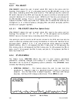
SPECTRAL DISPLAY –
This feature
allows the user to view real time
amplitude vs. frequency data in a graphical manner similar to a spectrum
analyzer. Use the Spin Knob to adjust frequency. Soft keys A/B change
step size. Soft keys C/D change vertical scale. Press
[PREV]
to exit.
Figure 4-3
Spectral Display
Summary of Contents for CG-1220
Page 6: ...vi THIS PAGE INTENTIONALLY LEFT BLANK...
Page 10: ...Table of Contents x THIS PAGE INTENTIONALLY LEFT BLANK...
Page 16: ......
Page 54: ...Maintenance 5 4 CG 1220 DTR THIS PAGE INTENTIONALLY LEFT BLANK...
Page 56: ...Engineering Drawings 6 2 CG 1220 DTR THIS PAGE INTENTIONALLY LEFT BLANK...
Page 65: ...Appendix C DTR Remote M C Protocol CG 6073 Rev R Jun 2012 4 THIS PAGE INTENTIONALLY LEFT BLANK...
Page 130: ...Remote M C Protocol C 2 CG 1220 DTR THIS PAGE INTENTIONALLY LEFT BLANK...
Page 134: ...Acronyms Abbreviations D 4 CG 1220 DTR THIS PAGE INTENTIONALLY LEFT BLANK...


