– 46 –
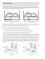
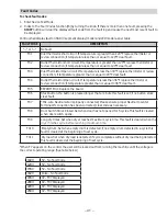
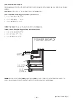
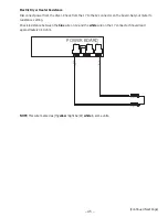
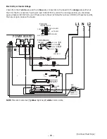
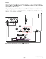
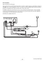
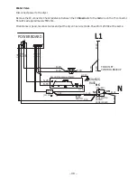
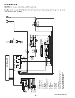
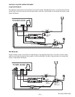
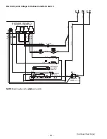
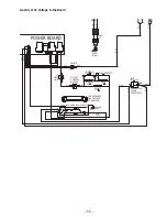
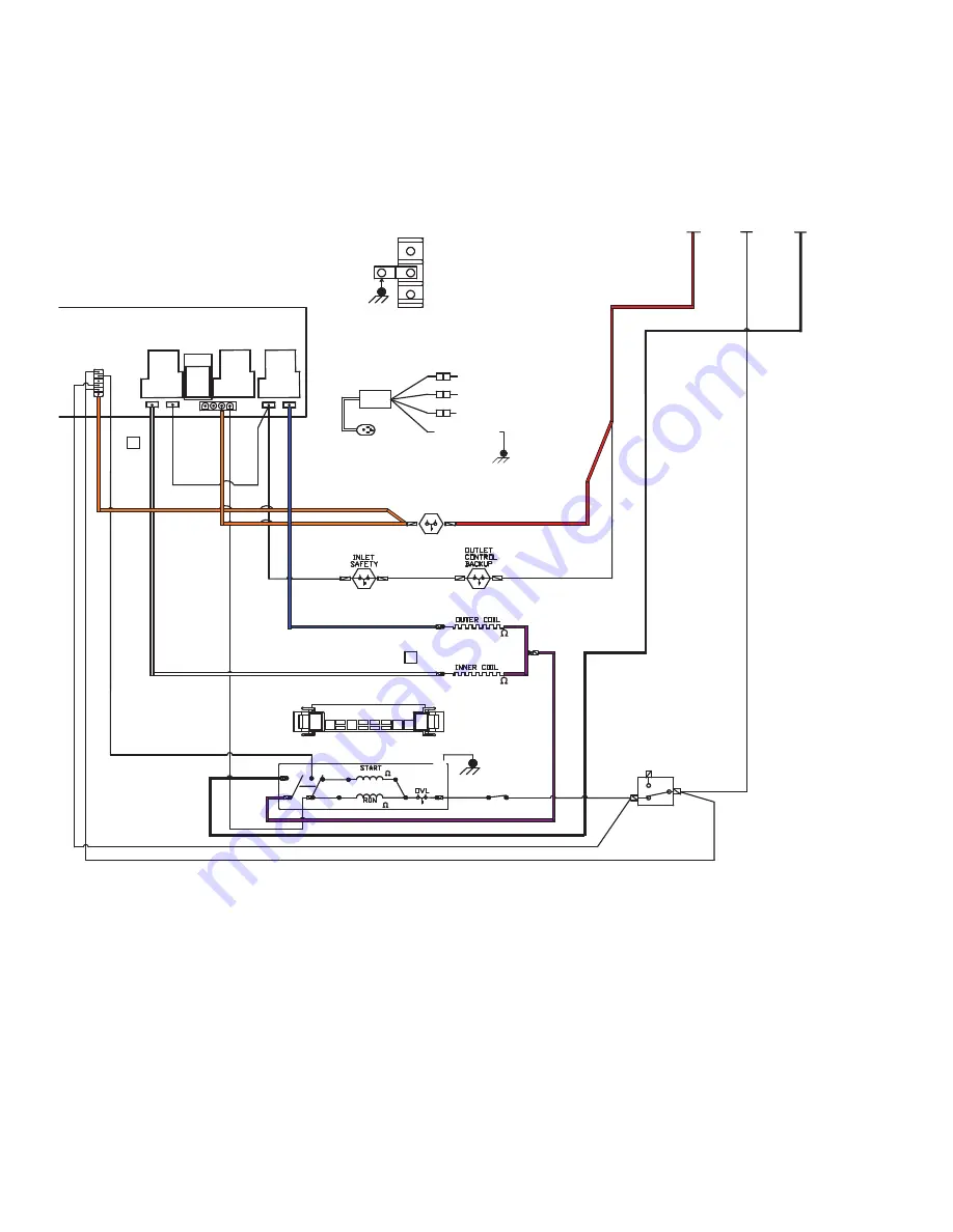
Electric Dryer Heater Voltage
Check from the J7 white wire and the J2 blue wire connectors on the board to the orange wires either at
the J8 or the J5 connectors. You should read 0 VAC. With the unit in the running position, you should see
approximately 240 VAC from any of these wires to the L2 terminal. If you show 240 VAC at these test points,
the relay is open, replace the board.
NOTE: This wire marked as (Y) yellow might be (W) white in some units.
(Continued Next Page)
L1 N L2
L1
N
L2
L1
N
L2
3
3
TAB SEQUENCE
DRUM MOTOR
CONNECTOR
Y-14
N-14
V-14
B-14
S-20
B-18
G
1
2
4
6
5
FOR USA
FOR CANADA
POWER BOARD
J8
J5
J4
J2
J7
J6
1
K4
K1
K3
K2
1
B-14
R-14
W-18
O-14
V-14
R-18
R-14
DOOR SWITCH
SHOWN
DOOR CLOSED
(NOT USED)
W-18
C-18
S-20
Y-14
O-14
O-18
R-18
O-14
R-14
N-14
O-18
W-18
C-18
O-18
O-18
B-18
W-18
V-14
5
6
4
G
P-18
DRUM MOTOR SHOWN STOPPED
CHASSIS
BASE
GY-14
IDLER
SWITCH
C-18
2
1
B-14
C-18
(21.18-19.95
)
(21.18-19.95
)
(3.19-3.53
)
(2.98-3.30
)
O-14
3
SEE NOTE 1
SEE NO
TE 1
TERMINAL BLOCK
CORD SET
HI-LIMIT
REAR PANEL
DRYER BACK
BLACK WIRES
WHITE WIRES
RED WIRES
REAR PANEL
STRAIN
RELIEF
RED WIRE
WHITE WIRE
BLACK WIRE
GROUND WIRE
GREEN
NC
NO
COM

