– 22 –
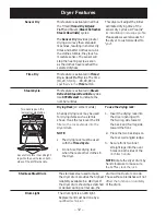
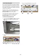
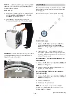
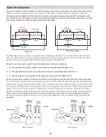
6. Close the door. Grasp the top of the front panel
RQERWKVLGHVWLOWLWRXWWKHQOLIWWKHSDQHORȺWKH
two bottom tabs.
Door Switch
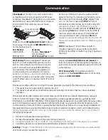
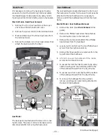
The door switch is fastened to the front panel by two
locking tabs (one on each side). When the dryer door
is closed, the switch will complete the drum motor
circuit, allowing dryer operation. When the door is
open, the switch will open the drum motor circuit,
interrupting dryer operation. Opening the dryer door
will also cause the drum light to be energized.
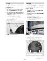
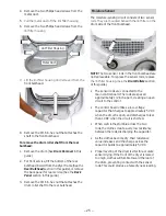
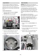
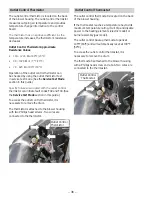
7KHGRRUVZLWFKFDQEHUHPRYHGE\LQVHUWLQJDÀDW
EODGHVFUHZGULYHUEHKLQGWKHVZLWFKÀDQJHDQG
carefully prying the switch out from the front panel.
Two wires are connected to the switch.
The door switch circuit can be checked in the
service mode.
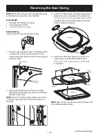
LED Drum Light
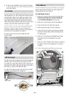
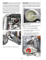
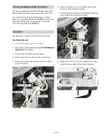
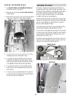
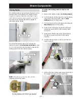
The LED drum light is attached to the front bulkhead
with two clips. To access the drum light, it will be
necessary to remove the top panel. It is necessary to
disconnect the drum light wire harness and squeeze
both clips to remove the LED drum light.
The LED drum light receives approximately 3.8 VDC
from the control board J11 connector.
Front Bulkhead
7KHIURQWEXONKHDGKRXVHVWKHOLQW¿OWHUKRXVLQJWZR
sensor rods, two front rollers, and drum light. It is
located behind the front panel.
Front Bulkhead Removal
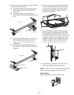
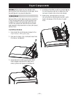
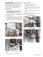
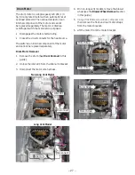
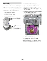
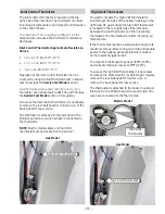
1. Remove the control, top, and front panels. (See
Control Panel Removal, Top Panel Removal,
and Front Panel Removal in this guide.)
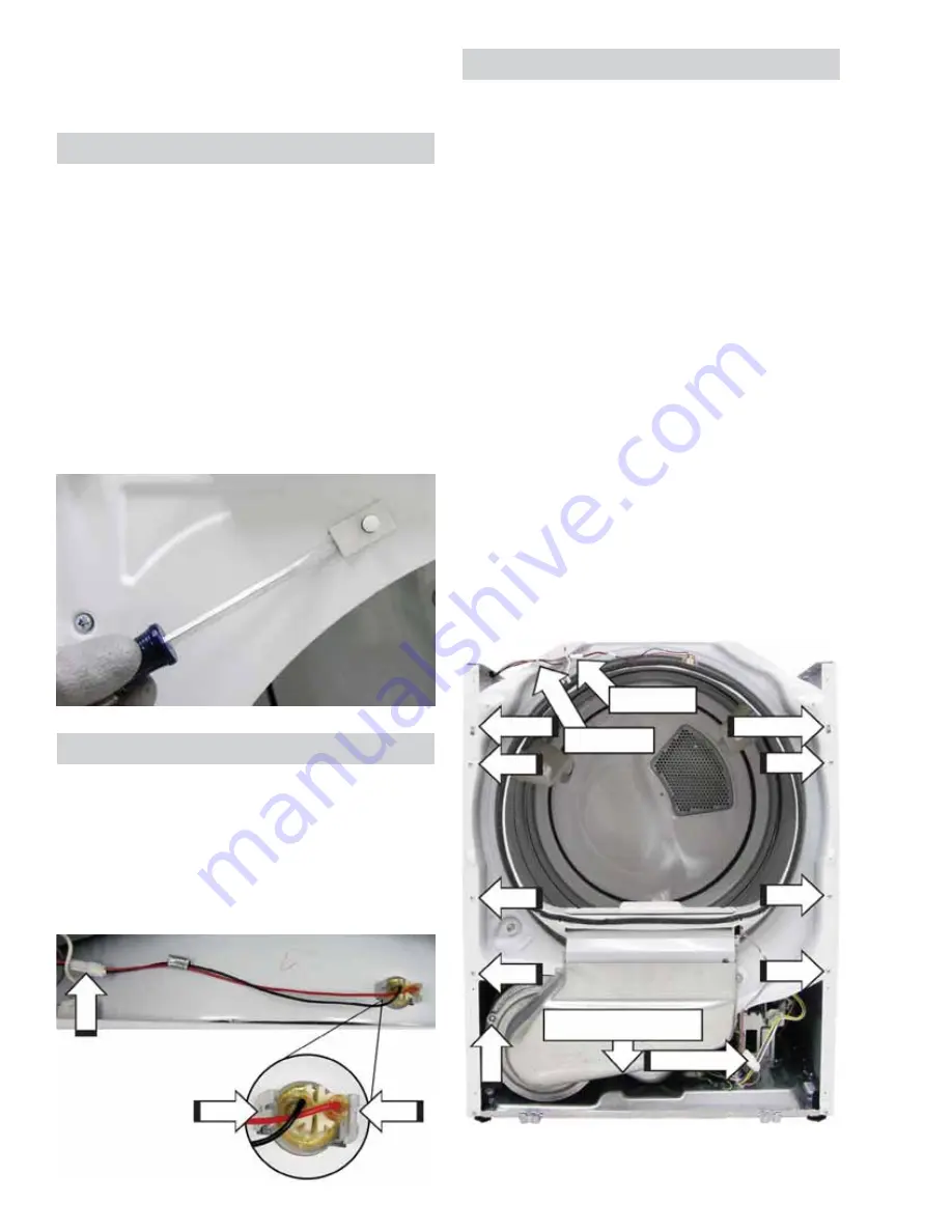
2. Remove the wire tie from the front bulkhead.
3. Disconnect the drum light wire harness.
4. Disconnect the sensor rods wire harness.
5. Loosen, but do not remove the top two Phillips
head screws that attach the front bulkhead to
the side panels.
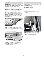
6. Remove the remaining six Phillips head screws
that attach the front bulkhead to the side
panels.
7. Remove the two Phillips head screws that attach
the bottom of the front bulkhead to the blower
housing.
8.
/LIWWKHIURQWEXONKHDGRȺWKHWRSWZRVFUHZV
Disconnect
Clip
Clip
Disconnect
Wire Tie
Loosen
Disconnect
Screw (below duct)
Loosen

