– 53 –
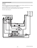
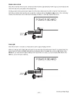
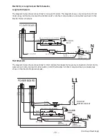
Gas Dryer Long Vent and Mist Schematics
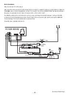
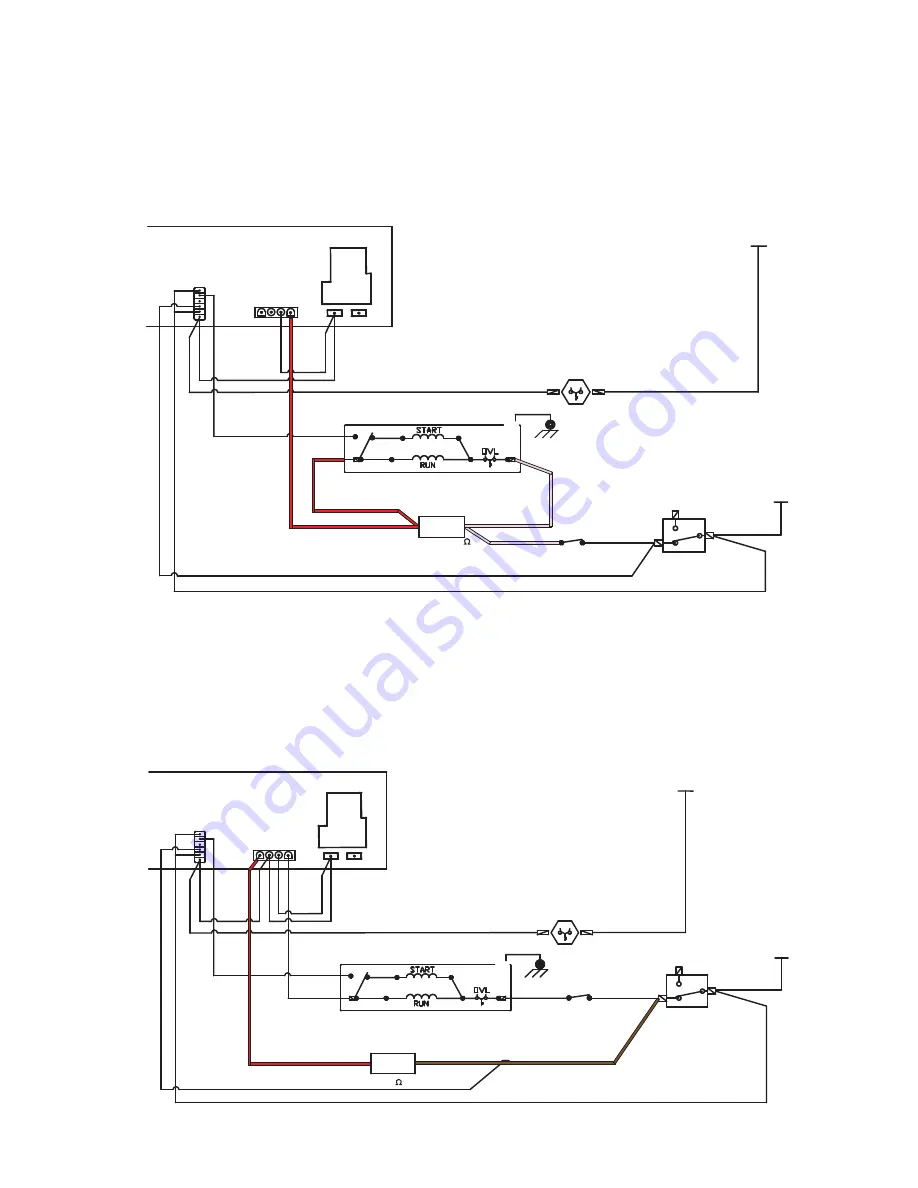
Long Vent Schematic
The diagram below shows connections for long vent models. This diagram shows only connection of drum
motor, long vent motor, door switch and idler switch. All other components are connected as shown in Gas
Model schematic.
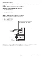
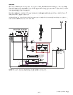
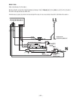
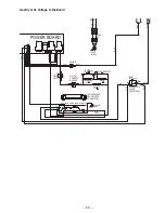
Mist Schematic
Diagram below shows connections for mist models. This diagram shows only connection of drum motor,
water valve, motor, door switch, idler switch, hi limit thermostat. All other components are connected as
shown in Gas Model schematic.
(Continued Next Page)
5
6
4
G
S-20
R-18
DRUM MOTOR SHOWN STOPPED
CHASSIS
BASE
GY-16
IDLER
SWITCH
C-18
DOOR SWITCH
SHOWN
DOOR CLOSED
(NOT USED)
W-18
C-18
W-18
WATER
VALVE
C-18
R-18
J5
1
POWER BOARD
R-18
J8
1
C-18 W-18
J4
J2
K3
V-18
V-18
S-20
V-18
V-18
V-18
B-18
B-18
R-18
V-18
V-18
P-18
C-18
(533-590)
3
V-18
NC
NO
COM
HI-LIMIT
L1
N
5
6
4
G
S-20
R-18
DRUM MOTOR SHOWN STOPPED
CHASSIS
BASE
GY-16
IDLER
SWITCH
C-18
DOOR SWITCH
SHOWN
DOOR CLOSED
(NOT USED)
W-18
C-18
W-18
BLOWER
MOTOR
P-18
P-18
R-18
R-18
J5
1
POWER BOARD
R-18
P-18
J8
1
C-18 W-18
J4
J2
K3
V-18
V-18
S-20
V-18
V-18
V-18
B-18
B-18
(14.25-15.75)
3
V-18
HI-LIMIT
NC
NO
COM
L1
N