– 34 –
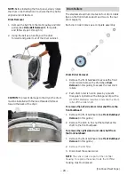
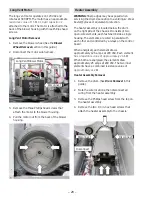
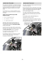
Gas Model - Rear Bulkhead Removal
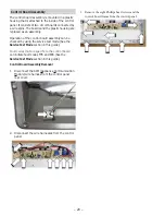
1. See
Electric Model - Rear Bulkhead Removal,
and follow steps 1 through 5.
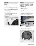
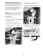
2. Remove the gas valve (see Gas Valve Removal
in this guide).
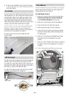
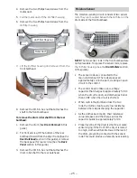
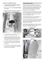
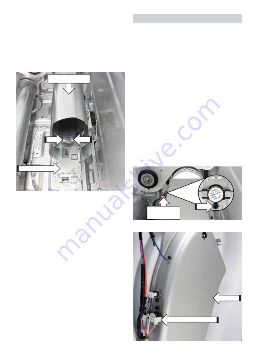
3. Remove the two 1/4 in. hex head screws and the
combustion tube from the burner pedestal.
4.
/LIWDQGPDQHXYHUWKHUHDUEXONKHDGRȺRIWKH
middle screws and combustion tube.
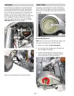
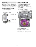
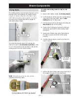
5. To access the inlet thermistor, high limit and
safety thermostats, water tube, spray nozzle
housing, and wire harnesses; tilt the top of the
rear bulkhead inward from the dryer frame.
6. To access the rear drum roller shafts, tilt the
bottom of the rear bulkhead inward from the
dryer frame.
7. To remove the rear bulkhead from the cabinet,
remove all wiring and water tubing attached to
the back of the rear bulkhead.
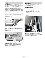
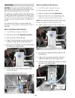
Inlet Safety Thermostat
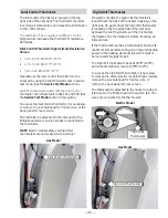
On electric models, the inlet safety thermostat is
located near the back of the heater housing, on the
left side. On gas models, the inlet safety thermostat
is located on the top right side of the inlet duct,
below the high limit thermostat. The thermostat
monitors incoming air temperature.
If the thermostat reaches a temperature beyond its
maximum temperature rating, it will trip and disable
power to the heating elements (electric model) or
burner assembly (gas model).
The inlet safety thermostat opens at 260°F (127°C)
and will automatically reset at 230°F (110°C).
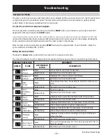
To access the inlet safety thermostat, it is necessary
to remove the drum (electric model). On gas models,
remove the rear bulkhead for front service, or the
back panel for rear service.
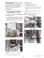
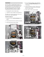
The thermostat is attached to the heater housing or
inlet duct with a Phillips head screw and a tab. Two
wires are connected to the thermostat.
Electric Model
Gas Model
Burner Pedestal
Combustion Tube
Inlet Safety Thermostat
Inlet Duct
Inlet Safety
Thermostat

