– 47 –
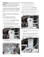
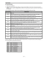
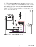
Gas Valve
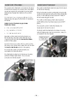
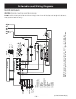
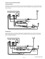
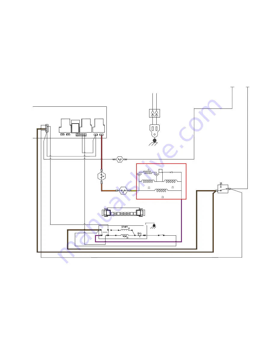
If no heat, with the dryer running and a heat cycle selected, check for 120 VAC to the gas burner assembly
from the J2 red wire to the brown wire on the J8. Approximate amperage draw of 3.5 amps can be checked
from the red wire on the J2 connector.
Also check between J4 and J2. If the relay is closed, no voltage should be present when calling for heat. If
voltage is present, replace the board.
,IYROWDJHLVSUHVHQWGLVFRQQHFWSRZHUIURPWKHGU\HU&KHFNLJQLWHUWKHUPRVWDWVÀDPHGHWHFWRUJDVYDOYH
coils, motor switch, harnesses, and connectors.
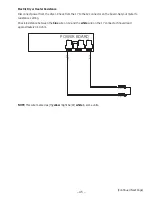
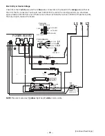
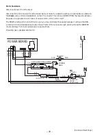
NOTE: This wire marked as (P) pink might be (W) white in some units.
(Continued Next Page)
3
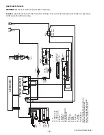
POWER BOARD
J8
J5
J4
J2
J7
J6
1
K4
K1
K3
K2
1
B-18
W-18
Y-18
P-18
P-18
V-18
V-18
V-18
Y-18
O-18
5
6
4
G
P-18
S-20
R-18
DRUM MOTOR
CHASSIS
BASE
GY-16
IDLER
SWITCH
C-18
V-18 R-18
TAB SEQUENCE
DRUM MOTOR
CONNECTOR
G 1
2
4
6
5
V-18
R-18
V-18
V-18
V-18
REAR
PANEL
CORD
SET
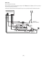
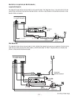
L1 N
W-18
B-18
B-18
DOOR SWITCH
SHOWN
DOOR CLOSED
(NOT USED)
C-18
C-18
W-18
W-18
2
1
C-18
C-18
C-18
(580 )
(1400 )
W-18
V-18
S-20
(40-400
)@75°F
3
(3.19-3.53 )
(2.98-3.30
)
R-18
SEE NO
TE 2
SEE NO
TE 2
HI-LIMIT
OUTLET
CONTROL
BACKUP
IGNITOR
INLE
T-
SA
FE
TY
FLAME DETECT
(1300 )
MAIN
BOOSTER
SAFETY
NC
NO
COM
L1 N
RUNNING