– 36 –
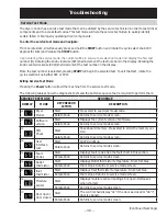
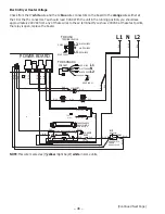
Outlet Control Thermistor
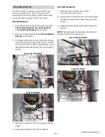
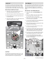
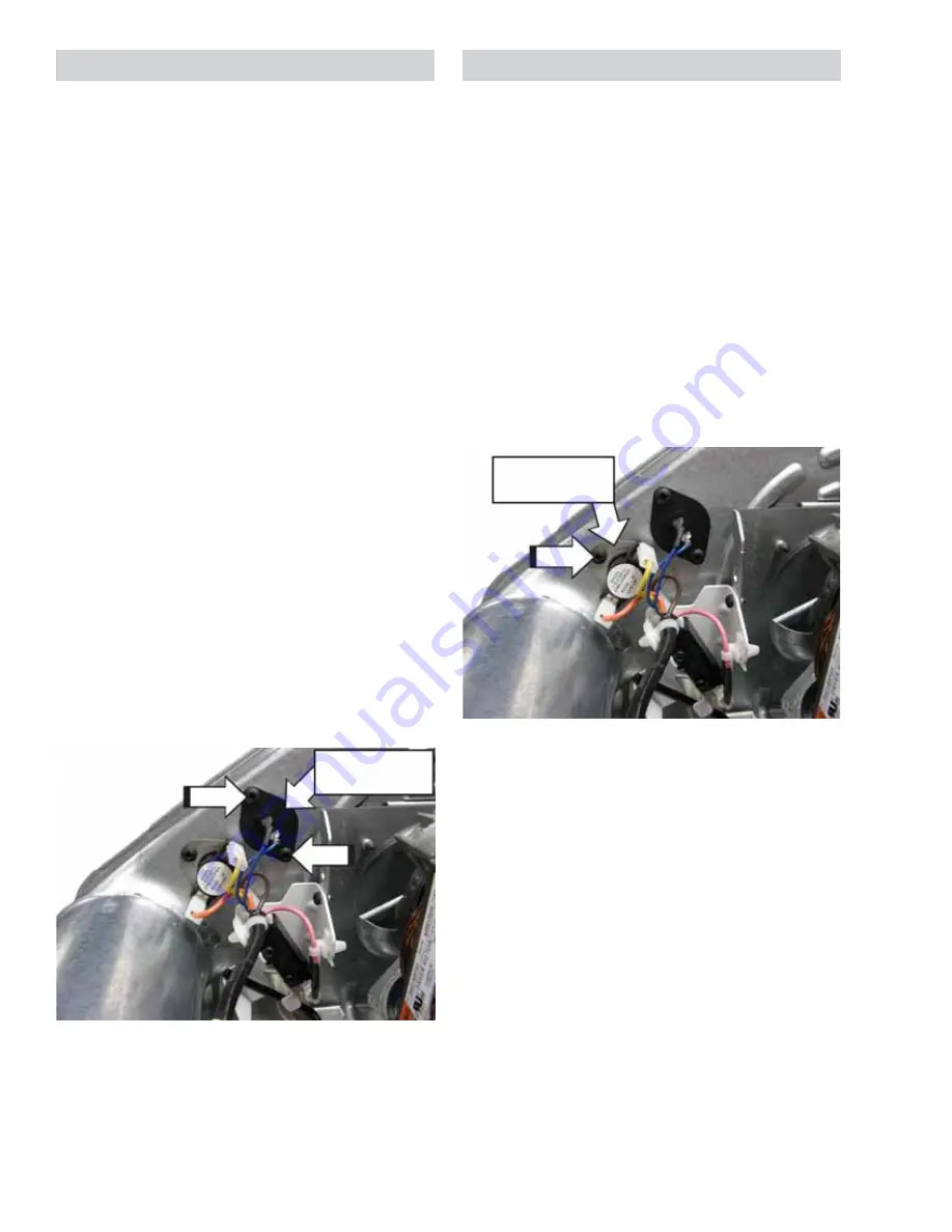
The outlet control thermistor is located on the back
of the blower housing. The outlet control thermistor
measures outgoing air temperature and provides
temperature change information to the control
board.
7KHWKHUPLVWRUKDVDQHJDWLYHFRHȻFLHQW$VWKH
temperature increases, the thermistor's resistance
decreases.
Outlet Control Thermistor Approximate
Resistance Values:
•
.DW)&
•
.DW)&
•
.DW)&
Operation of the outlet control thermistor can
be checked by using the outlet thermistor test
in service test mode. (See the Service Test Mode
section in this guide.)
6SHFL¿FIDLOXUHVDVVRFLDWHGZLWKWKHRXWOHWFRQWURO
thermistor can initiate fault codes F02 and F04. (See
the Service Test Mode section in this guide.)
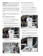
To access the outlet control thermistor, it is
necessary to remove the drum.
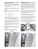
The thermistor is attached to the blower housing
with two Phillips head screws. Two wires are
connected to the thermistor.
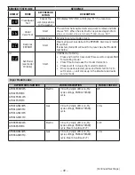
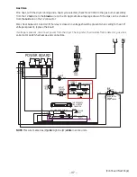
Outlet Control Thermostat
The outlet control thermostat is located on the back
of the blower housing.
If the thermostat reaches a temperature beyond its
maximum temperature rating, it will trip and disable
power to the heating elements (electric model) or
burner assembly (gas model).
The outlet control backup thermostat opens at
145°F (63°C) and will automatically reset at 130°F
(54°C).
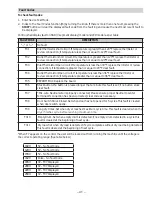
To access the outlet control thermostat, it is
necessary to remove the drum.
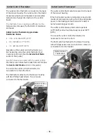
The thermostat is attached to the blower housing
with a Phillips head screw and a tab. Two wires are
connected to the thermostat.
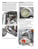
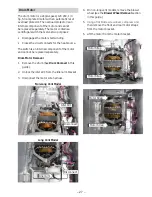
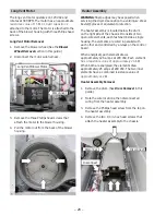
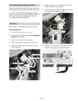
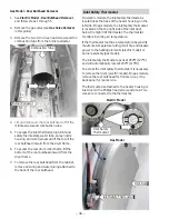
Outlet Control
Thermistor
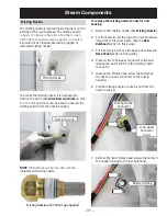
Outlet Control
Thermostat

