170
Chapter 7: Adding or Replacing Components
www.gateway.com
9
Connect the drive’s data and power cables. The red-striped edge of the data
ribbon cable indicates Pin 1 and corresponds with Pin 1 on the drive
(typically on the side farthest from the power supply connection). See the
drive documentation for further instructions.
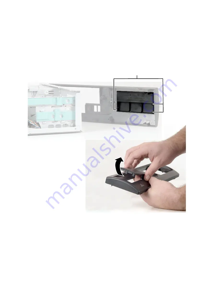
10
Press in on the four bezel cover release tabs, then remove the bezel cover.
Store the bezel cover in a safe place in case you have to reinstall it.
Bezel release tabs
Summary of Contents for e-4000
Page 1: ......
Page 2: ......
Page 108: ...102 Chapter 6 Restoring Software www gateway com...
Page 115: ...109 Gateway Mid Tower Case www gateway com 7 Pull the side panel away from the case...
Page 138: ...132 Chapter 7 Adding or Replacing Components www gateway com 9 Lift the side panel up...
Page 139: ...133 Gateway Micro Tower Case www gateway com 10 Lift the side panel away from the case...
Page 155: ...149 Gateway Micro Tower Case www gateway com 5 Swing the add in card retention cover open...
Page 196: ...190 Chapter 7 Adding or Replacing Components www gateway com...
Page 202: ...196 Chapter 8 Using the BIOS Setup Utility www gateway com...
Page 232: ...226 Chapter 9 Troubleshooting support gateway com...
Page 250: ...244 Appendix B Safety Regulatory and Legal Information www gateway com...
Page 258: ...252...
Page 259: ......
Page 260: ...MAN US E4000 SYS GDE R2 12 02...


