8
Chapter 1: Checking Out Your Gateway E-4000 Computer
www.gateway.com
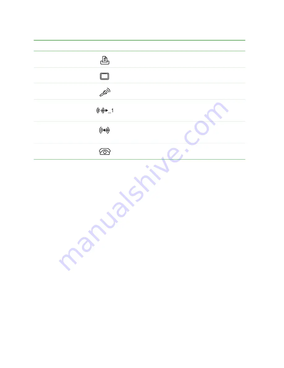
Parallel port
Plug a parallel device (such as a printer) into this port.
Monitor port
Plug a monitor into this port.
Microphone jack
Plug a microphone into this jack. This jack is color-coded
red or pink.
Headphone/speakers
(Line out) jack
Plug powered, analog front speakers, an external
amplifier, or headphones into this jack. This jack is
color-coded green.
Audio input (Line in) jack
Plug an external audio input source (such as a stereo)
into this jack so you can record sound on your computer.
This jack is color-coded blue.
Telephone jack
(optional)
If your modem has a telephone jack, plug the cable for
a telephone into this jack.
Component
Icon
Description
Summary of Contents for e-4000
Page 1: ......
Page 2: ......
Page 108: ...102 Chapter 6 Restoring Software www gateway com...
Page 115: ...109 Gateway Mid Tower Case www gateway com 7 Pull the side panel away from the case...
Page 138: ...132 Chapter 7 Adding or Replacing Components www gateway com 9 Lift the side panel up...
Page 139: ...133 Gateway Micro Tower Case www gateway com 10 Lift the side panel away from the case...
Page 155: ...149 Gateway Micro Tower Case www gateway com 5 Swing the add in card retention cover open...
Page 196: ...190 Chapter 7 Adding or Replacing Components www gateway com...
Page 202: ...196 Chapter 8 Using the BIOS Setup Utility www gateway com...
Page 232: ...226 Chapter 9 Troubleshooting support gateway com...
Page 250: ...244 Appendix B Safety Regulatory and Legal Information www gateway com...
Page 258: ...252...
Page 259: ......
Page 260: ...MAN US E4000 SYS GDE R2 12 02...


