


Page C-24
G900X/G950 Installation and Maintenance Manual – PICP & Warranty Registration
Revision D
190-00719-00
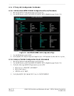
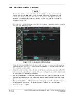
C.2.4 GIA 63W Testing
C.2.4.1 VHF COM Interference Test
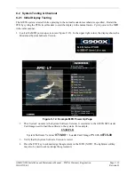
Garmin recommends that the installer perform a general post installation communications check to verify
there are no undesirable noise elements present when transmitting or receiving with the communication
radios.
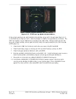
This test must be conducted outside and away from buildings. Use of a GPS repeater inside a hangar may
result in a failed test. This procedure assumes that the system is currently set to 25 kHz COM channel
spacing. Once the signal acquisition test from Section C.2.2 has been completed successfully, perform
the following steps:
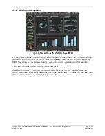
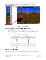
1.
On the MFD, monitor GPS signal strength bars on the 3
rd
AUX page.
2.
On the PFD, ensure that the CDI is set to GPS. If it is not, press the ‘CDI’ softkey until GPS
ENR is displayed.
3.
Verify that the GPS “INTEG” flag is out of view.
4.
Select 121.150 MHz on the No. 1 COM transceiver.
5.
Transmit for a period of 35 seconds while monitoring GPS 1 signal strength levels.
6.
During the transmit period, verify that the GPS “INTEG” flag does not come into view on the
PFD and verify that GPS 1 does not lose a 3-D navigation solution on the MFD.
7.
Repeat steps 5 and 6 and re-transmit while monitoring GPS 2 signal levels on the MFD.
8.
Repeat steps 4 through 7 for each of the following frequencies:
•
121.175 MHz
•
121.200 MHz
•
131.250 MHz
•
131.275 MHz
•
131.300 MHz
9.
Repeat steps 4 through 8 for the No. 2 COM transceiver (GIA2).
10.
On the MFD, select the 4
th
AUX page.
11.
Under the COM CONFIG field, change the COM channel spacing from 25 kHz to 8.33 kHz.
12.
Go back to the 3
rd
AUX page.
13.
Select 121.185 MHz on the No. 1 COM transceiver.
14.
Transmit for a period of 35 seconds while monitoring GPS 1 signal strength levels.
15.
During the transmit period, verify that the GPS “DR” or “LOI” flags do not come into view on
the PFD HSIhis and verify that GPS 1 does not lose a 3-D navigation solution on the MFD.
16.
Repeat steps 14 and 15 and re-transmit while monitoring GPS 2 signal levels on the MFD.
17.
Repeat steps 14 through 16 for each of the following frequencies:
•
121.190 MHz
•
130.285 MHz
•
131.290 MHz
18.
Repeat steps 14 through 17 for the No. 2 COM transceiver (GIA2).
19.
On the MFD, select the 4
th
AUX page and change the COM channel spacing back to 25 kHz.


