


G900X/G950 Installation and Maintenance Manual – Software, Configuration, and Calibration
Page 15-51
190-00719-00
Revision D
15.4.5 Cockpit Lighting Setup
The following guidance is recommended to help the technician determine a suitable setup. A test flight is
recommended upon completion of the setup.
NOTE
To accurately configure the lighting, the ability to adjust ambient light conditions is
required. The technician should be prepared to simulate complete darkness in the
cockpit. Simply covering the photocells may not allow the technician’s eyes to properly
judge whether the display brightness is too bright, or too dim, for night use.
Photocell Configuration
:
1.
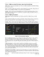
It is recommended to start configuration with a linear lighting curve slope (45° Straight Line).
2.
Minimize photocell input levels by simulating night conditions in the cockpit. Any other
instrument panel or cockpit lighting should be turned on for this adjustment. Seek uniform
consistency between display lighting, bezel/key lighting, and any other illuminated objects.
a)
If a display/keypad is too bright, lower the minimum setting and/or adjust the lighting
curve to achieve the desired brightness.
b)
If the display is not bright enough, raise the minimum setting to the desired
brightness.
c)
In the case of the GMA, adjust gain and offset settings to achieve the desired
brightness relative to other lighting.
3.
Simulate direct maximum sunlight in the cockpit (best if done outside).
a)
Verify that the display produces maximum brightness on the graph.
4.
Simulate average sunlight conditions in the cockpit (between ~50-75% input level).
a)
If the display is too bright or too dim, use a combination of lighting curve changes to
achieve desired brightness at mid-range lighting input levels.
b)
Ensure that the lighting curve and minimum setting still maintain the low-light
configuration achieved in Step 2. Repeat Step 2 if necessary to re-adjust night
lighting settings.
c)
Adjust the response time to smooth changes to brightness as required.
Dimmer Bus Configuration
:
1.
Select the appropriate source voltage for the dimmer bus. Set the Photo Transition point to
0.0 for initial dimmer knob calibration.
2.
Simulate night conditions in the cockpit. Turn the dimmer bus knob to its minimum setting
and observe the graph for corresponding change to the input level. Attempt to seek uniform
consistency between display lighting, bezel key lighting, and any other cockpit illuminated
information.
a)
If a display/keypad is too bright, lower the minimum setting and/or adjust the lighting
curve to achieve the desired brightness.
b)
If the display is too dim, increase the minimum setting to achieve desired levels.
c)
In the case of the GMA, adjust gain and offset settings to achieve the desired
brightness relative to other lighting.


