


G900X/G950 Installation and Maintenance Manual – Pinouts
Page A-39
190-00719-00
Revision D
A.3.13 VOR/ILS Indicator
A.3.14 VOR/ILS Indicator Function
The VOR/ILS indicator displays both lateral and vertical, To/From indications, lateral flags, vertical
flags, and superflags.
VOR/LOC COMPOSITE OUT is a standard VOR/Localizer Composite signal which may be used to
drive the Left/Right, TO/FROM, and Flag indications of certain navigational indicators that contain an
internal converter.
The ILS ENERGIZE output goes low when the VLOC frequency is channeled to a localizer channel.
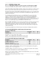
A.3.15 VOR/ILS Indicator Electrical Characteristics
A.3.15.1 Superflags
Pin Name
Connector
Pin
I/O
VOR/LOC SUPERFLAG
P602
15
Out
GLIDESLOPE SUPERFLAG
P602
38
Out
The output supplies not less than 500 mA on a 28 volt system with the output voltage not less than
(AIRCRAFT POWER – 1.5 VDC) when the flag is to be OUT OF VIEW. The output voltage with
respect to ground is less than 0.25 VDC when the flag is to be IN VIEW.
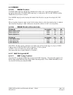
A.3.15.2 Deviation
Pin Name
Connector
Pin
I/O
VOR/LOC +LEFT
P602
5
Out
VOR/LOC +RIGHT (VOR/LOC COMMON)
P602
6
--
GLIDUP
P602
34
Out
GLIDDOWN (GLIDESLOPE COMMON)
P602
55
--
The deviation outputs are each capable of driving up to three 1000
Ω
meter loads with
±
150 mVDC
±
10% with respect to 2.5V Common for full-scale deflection. The drive circuit provides for more than
full-scale deflection with a maximum course deviation output voltage of ±300 mVDC
±
10%.
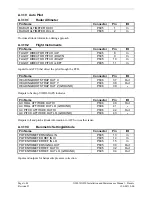
A.3.15.3 To/From
Pin Name
Connector
Pin
I/O
VOR/LOC +TO
P602
1
Out
VOR/LOC +FROM (VOR/LOC COMMON)
P602
2
--
The output is capable of driving up to three 200
Ω
meter loads. When indicating TO, the output is
+225 ±75 mVDC
.
When indicating FROM, output is -225 ±75 mVDC
.
When invalid information is
present (Flag IN VIEW) the TO/FROM output is 0 ±10 mVDC
.


