


Page A-70
G900X/G950 Installation and Maintenance Manual – Pinouts
Revision D
190-00719-00
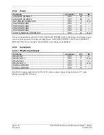
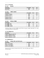
A.7.2 Power
Pin Name
Connector
Pin
I/O
AIRCRAFT POWER 1
P3301
21 In
AIRCRAFT POWER 1
P3301
42 In
AIRCRAFT POWER 2
P3301
56 In
AIRCRAFT POWER 2
P3301
60 In
SWITCHED POWER OUT
P3301
62 Out
XPDR REMOTE POWER OFF
P3301
54 In
POWER GROUND
P3301
27 --
POWER GROUND
P3301
43 --
SIGNAL GROUND
P3301
51 --
SIGNAL GROUND
P3301
58 --
Power Input requirements are listed in the following tables. The power-input pins accept 14/28 VDC.
Switched Power Out is a power source available for devices such as a remote digital altitude encoder.
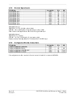
A.7.3 Temperature
Inputs
Pin Name
Connector
Pin
I/O
CURRENT TEMPERATURE PROBE OUT
P3301
41 Out
CURRENT TEMPERATURE PROBE IN
P3301
44 In
Temperature function is provided for the external display system via input to the GTX 33 transponder.
The temperature input is used for Outside Air Temperature (OAT) display and Density Altitude
computations. The type of temperature probe required is a current sensor type, such as a Garmin GTP 59
or an AD590-KH or AD592 made by Analog Devices. The GTX 33 is not configurable for different
types of temperature sensors. The temperature-input specification is 1 micro amp per degree Kelvin
(1 uA/°K).


