


Page 11-4
G900X/G950 Installation and Maintenance Manual – GWX 68
Revision D
190-00719-00
11.5 Installation Requirements
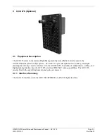
11.5.1 Required
Accessories
Table 11-3. GWX 68 Accessories
Item Garmin
P/N
GWX 68 Installation Kit
011-01114-00
11.6 Installation
Considerations
The GWX 68 is designed to be rigidly mounted in the nose section of the aircraft. If the nose section is
not accessible, pod mounting is possible. The bulk head or antenna mounting plate must be very close to
perpendicular to the aircraft center line. The selected location must have adequate clearance for the full
antenna sweep and tilt range. See Appendix E for outline and installation drawings. The nose section
does not need to be pressurized.
NOTE
It is crucial to the performance of the GWX 68 weather radar system that care be taken in
alignment of the GWX 68 unit with respect to the aircraft.
Fabrication of a wiring harness is required. Sound mechanical and electrical methods and practices are
required for installation of the GWX 68.
NOTE
Special care should also be taken to avoid any contact between tools that could become
magnetized and the magnetron. Use of non-magnetic tools (e.g. beryllium copper or
titanium) is recommended when installing or servicing the GWX 68.
11.7 Mounting
Requirements
The GWX 68 mounting surface must be capable of providing structural support and electrical bond to the
aircraft to minimize radiated EMI and provide protection from High-Intensity Radiation Fields (HIRF).
11.8 Unit Installation
1.
Refer to Appendix E to mount the GWX 68 using the hardware provided.
2.
Assemble the GWX 68 connector kit (see instructions below).
3.
Check the unit for clearance in all extreme positions.
4.
Ensure wiring harness is routed in such a way that is cannot be struck by or interfere with the
unit movement through the full sweep and tilt range.


