


G900X/G950 Installation and Maintenance Manual – Non LRU Specific Installation Information
Page 13-5
190-00719-00
Revision D
Table 13-5. Shielded Cable Preparations for Garmin Connectors
Backshell
Size
Number
of Pins
Std/HD
Float
Min
(inches)
Float
Max
(inches)
Ideal
Float
(inches)
Window
Min
(inches)
Window
Max
(inches)
Ideal
Window
(inches)
1 9/15
1.25
2.25
1.75
2.75
5.25
4.25
2 15/26
1.5 2.5 2.0 3.0 5.5 4.5
3 25/44
1.5 2.5 2.0 3.0 5.5 4.5
4 37/62
1.5 2.5 2.0 3.0 5.5 4.5
5 50/78
1.5 2.5 2.0 3.0 5.5 4.5
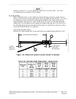
2.
At one end of a shielded cable (item 4) measure a distance between “Window Min” to “Window
Max” (Table 13-5) and cut a window (max size 0.35”) in the jacket to expose the shield (see
Figure 13-2). Use caution when cutting the jacket to avoid damaging the individual braids of the
shield. When dealing with a densely populated connector with many cables, it may prove
beneficial to stagger the windows throughout the “Window Min” to “Window Max” range. If
staggering is not needed the “Ideal Window” length is recommended.
Suggested tools to accomplish the window cut:
•
Coaxial Cable Stripper
•
Thermal Stripper
•
Sharp Razor Blade
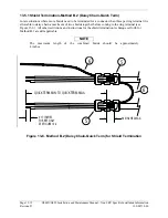
3.
Connect a Flat Braid (item 6) to the shield exposed through the window of the prepared cable
assembly (item 4) from step 2. The Flat Braid should go out the front of the termination towards
the connector. It is not permitted to exit the rear of the termination and loop back towards the
connector (see Figure 13-2). Make this connection using an approved shield termination
technique.
NOTE
FAA AC 43.13-1B Chapter 11, Section 8 (Wiring Installation Inspection Requirements)
may be a helpful reference for termination techniques.
Preferred Method:
Slide a solder sleeve (item 5) onto the prepared cable assembly (item 4) and connect the
Flat Braid (item 6) to the shield using a heat gun approved for use with solder sleeves. It
may prove beneficial to use a solder sleeve with a pre-installed Flat Braid versus having
to cut a length of Flat Braid to be used. The chosen size of solder sleeve must
accommodate both the number of conductors present in the cable and the Flat Braid (item
6) to be attached.


