


G900X/G950 Installation and Maintenance Manual – GRS 77 and GMU 44
Page 7-9
190-00719-00
Revision D
7.8 Unit
Installation
NOTE
When mounting the GRS 77 rack to the airframe, and the unit to the rack, it is
important to ensure that fastening hardware is tight for proper unit operation.
Use a #2 Phillips screwdriver to tighten the GRS 77 to the rack, rather than
hand tightening the knurled screws. The recommended torque is 22-25 inch
pounds.
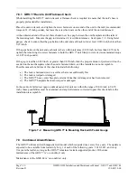
After ensuring that requirements are met, assemble the GRS 77 and GMU 44 mounting plate kits
according to the dimensions given in Appendix E. Install the unit assemblies. While installing the
GRS 77 on its rack, perform the flatness check described in Section 7.10.1. After completion, tighten the
four mounting screws securing the GRS 77 unit to the rack.
Mount the GMU 44 to its mounting plate, taking care to tighten the mounting screws firmly.
The metal components in the GMU 44's connector may slightly affect the magnetic field sensed by the
GMU 44. Place the connector at least 2 inches from the body of the GMU 44 to minimize this effect.
After attaching the GMU 44's connector to its mate in the aircraft wiring, secure the connector in place
using good installation practices. This will ensure that any remaining magnetic effect can be
compensated for using Calibration Procedure B: Magnetometer Calibration.
If the GMU 44 is ever removed, the anti-rotation properties of the mounting screws must be restored.
This may be done by replacing the screws with new Garmin PN 211-60037-08. If original screws must
be re-used, coat screw threads with Loctite 242 (blue) thread-locking compound, Garmin PN
291-00023-02, or equivalent. Important: Mounting screws must be brass.


