7-4
7.1 Setup Mode
■
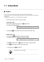
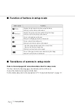
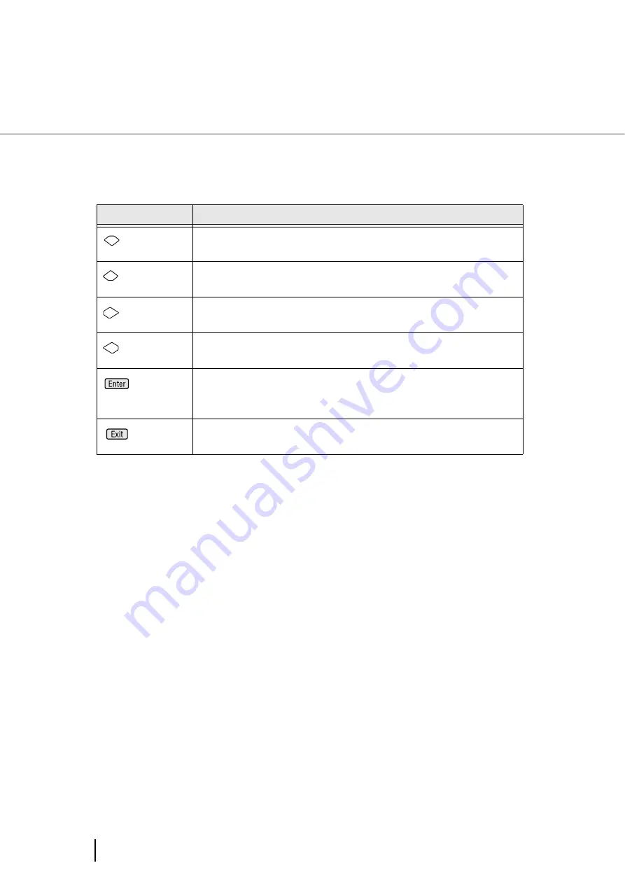
Function of buttons in setup mode
■
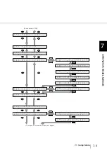
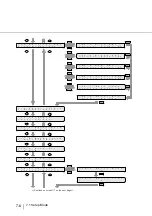
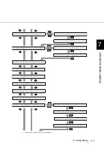
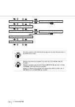
Transitions of screens in setup mode
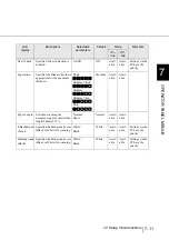
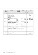
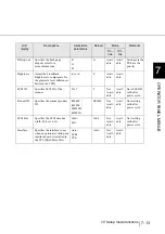
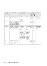
Refer to the next page LCD screen transitions chart for setup mode.
The flow chart in the following pages show transition of the LCD screen.
Some of the details are not expressed in the chart.
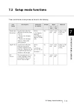
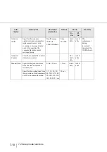
For the details, please refer to the descriptions in "7.2 Setup mode functions" on page 7-9.
Button name
Function
[Next]
Displays the next menu item without saving the change.
Referred to as Next button in this manual.
[Previous]
Displays the previous menu item without saving the change.
Referred to as Previous button in this manual.
Moves to the right item on the menu
Referred to as Right arrow button in this manual.
Moves to the left item on the menu
Referred to as Left arrow button in this manual.
- Saves the change and then displays the next menu item
- Moves to the lower level menu item
Referred to as Enter button in this manual.
Moves to the upper level menu item without saving the change
Referred to as Exit button in this manual.
Summary of Contents for 4860C - fi - Document Scanner
Page 1: ...Operator s Guide fi 4860C2 Image Scanner P3PC 1692 01ENZ0 ...
Page 2: ......
Page 22: ... xx ...
Page 26: ... xxiv ...
Page 140: ...4 6 4 3 Replacing the Pad ASSY Pad cleaning area Pad ASSY Guide plate ...
Page 158: ...4 24 4 7 Replacing the Back side Lamp ...
Page 190: ...5 32 5 4 Labels on the Scanner ...
Page 288: ...8 6 8 4 fi 486TRK Thinner paper Roller Kit ...
Page 294: ...9 6 9 3 Dimensions ...
Page 312: ... AP 18 ...


