


Fast Ethernet Controller (FEC)
MCF52235 ColdFire® Integrated Microcontroller Reference Manual, Rev. 6
18-4
Freescale Semiconductor
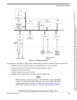
The RAM is the focal point of all data flow in the Fast Ethernet Controller and is divided into transmit and
receive FIFOs. The FIFO boundaries are programmable using the FRSR register. User data flows to/from
the DMA block from/to the receive/transmit FIFOs. Transmit data flows from the transmit FIFO into the
transmit block and receive data flows from the receive block into the receive FIFO.
The user controls the FEC by writing, through the SIF (Slave Interface) module, into control registers
located in each block. The CSR (control and status register) block provides global control (e.g. Ethernet
reset and enable) and interrupt handling registers.
The MII block provides a serial channel for control/status communication with the external physical layer
device (transceiver). This serial channel consists of the EMDC (Management Data Clock) and EMDIO
(Management Data Input/Output) lines of the MII interface.
The DMA block provides multiple channels allowing transmit data, transmit descriptor, receive data and
receive descriptor accesses to run independently.
The Transmit and Receive blocks provide the Ethernet MAC functionality (with some assist from
microcode).
The Message Information Block (MIB) maintains counters for a variety of network events and statistics.
It is not necessary for operation of the FEC but provides valuable counters for network management. The
counters supported are the RMON (RFC 1757) Ethernet Statistics group and some of the IEEE 802.3
counters. See
Section 18.5.3, “MIB Block Counters Memory Map
” for more information.
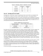
18.4
Functional Description
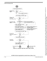
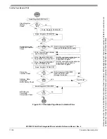
This section describes the operation of the FEC, beginning with the hardware and software initialization
sequence, then the software (Ethernet driver) interface for transmitting and receiving frames.
Following the software initialization and operation sections are sections providing a detailed description
of the functions of the FEC.
18.4.1
Initialization Sequence
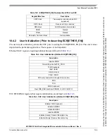
This section describes which registers are reset due to hardware reset, which are reset by the FEC RISC,
and what locations the user must initialize prior to enabling the FEC.
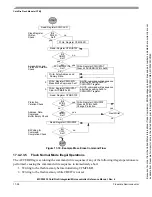
18.4.1.1
Hardware Controlled Initialization
In the FEC, registers and control logic that generate interrupts are reset by hardware. A hardware reset
deasserts output signals and resets general configuration bits.
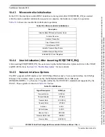
Other registers reset when the ECR[ETHER_EN] bit is cleared. ECR[ETHER_EN] is deasserted by a hard
reset or may be deasserted by software to halt operation. By deasserting ECR[ETHER_EN], the
configuration control registers such as the TCR and RCR are not reset, but the entire data path is reset.
Because
of
an
order
from
the
United
States
International
Trade
Commission,
BGA-packaged
product
lines
and
part
numbers
indicated
here
currently
are
not
available
from
Freescale
for
import
or
sale
in
the
United
States
prior
to
September
2010:MCF52234CVM60,
MCF52235CVM60


