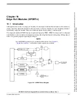


Edge Port Modules (EPORTn)
16-2
Freescale Semiconductor
MCF52235 ColdFire® Integrated Microcontroller Reference Manual, Rev. 6
NOTE
The GPIO module must be configured to enable the peripheral function of
the appropriate pins (refer to
Chapter 14, “General Purpose I/O Module”
)
prior to configuring the edge-port module.
16.2
Low-Power Mode Operation
This section describes the operation of the EPORT module in low-power modes. For more information on
low-power modes, see
Chapter 9, “Power Management”.
shows EPORT-module operation in
low-power modes and describes how this module may exit each mode.
NOTE
The low-power control register (LPCR) in the system control module
specifies the interrupt level at or above what is needed to bring the device
out of a low-power mode.
In wait and doze modes, the EPORT module continues to operate as it does in run mode. It may be
configured to exit the low-power modes by generating an interrupt request on a selected edge or a low level
on an external pin. In stop mode, no clocks are available to perform the edge-detect function. Only the
level-detect logic is active (if configured) to allow any low level on the external interrupt pin to generate
an interrupt (if enabled) to exit stop mode.
NOTE
In stop mode, the input pin synchronizer is bypassed for the level-detect
logic because no clocks are available.
16.3
Signal Descriptions
All EPORT pins default to general-purpose input pins at reset. The pin value is synchronized to the rising
edge of CLKOUT when read from the EPORT pin data register (EPPDR). The values used in the
edge/level detect logic are also synchronized to the rising edge of CLKOUT. These pins use
Schmitt-triggered input buffers with built-in hysteresis designed to decrease the probability of generating
false, edge-triggered interrupts for slow rising and falling input signals.
When a pin is configured as an output, it is driven to a state whose level is determined by the corresponding
bit in the EPORT data register (EPDR). All bits in the EPDR are set at reset.
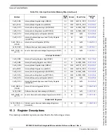
Table 16-1. Edge Port Module Operation in Low-Power Modes
Low-power Mode
EPORT Operation
Mode Exit
Wait
Normal
Any IRQn interrupt at or above level in LPCR
Doze
Normal
Any IRQn interrupt at or above level in LPCR
Stop
Level-sensing only
Any IRQn interrupt set for level-sensing at or
above level in LPCR. See note below.
Because
of
an
order
from
the
United
States
International
Trade
Commission,
BGA-packaged
product
lines
and
part
numbers
indicated
here
currently
are
not
available
from
Freescale
for
import
or
sale
in
the
United
States
prior
to
September
2010:MCF52234CVM60,
MCF52235CVM60


