


Page 69
© 2011 Fluke Calibration
Note
•
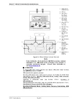
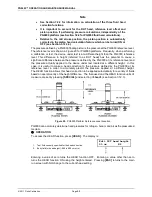
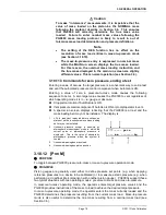
The DUT head height should be entered as a positive value if the device or
system under test is above the PG9000 reference level and negative if it is
below (see Figure 20).
•
The reference level is indicated by a marking on the mounting post or may
be determined as a distance of 16.4 mm from the lip of the platform
baseplate (see Figure 20).
•
To change units of DUT head height between inches and centimeters and
to change the test fluid, press [SPECIAL] and select <3Head> (see Section
3.12.3).
•
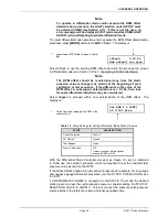
When the HEAD function is ON the application of a head correction is
indicated by <h> in the right side of the top line of the MAIN run screen
(see Section 3.8). When the HEAD function is OFF, the <h> is NOT shown.
PG9000’s also have a separate head correction to compensate for the
deviation between the current piston position and mid-stroke
(see Section 3.12.3.4). This PISTON head can be turned ON and OFF.
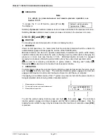
3.10.8 [ROTATE]
PURPOSE
To turn automatic control of motorized piston rotation (acceleration and brake) ON and OFF.
Note
See Section 3.10.13 for information on manual control of motorized piston
rotation.
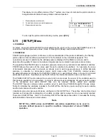
PRINCIPLE
The motorized piston rotation system is used to start or increase piston rotation when the
piston is floating. It is also used to stop piston rotation when necessary, for example before
manipulating mass to set a new pressure.
The system operates on an as-needed basis – it engages only when required to bring the
rotation rate up to speed, and then it disengages allowing the piston to freely rotate. It rotates
the piston by engaging a motor driven belt around the bottom of the mass loading bell to
accelerate or brake the rotation rate of the mass bell and piston. The motorized rotation
system can engage with the piston at any position in its stroke and at any rotation speed with
minimal impact on piston position and the defined pressure. When the motorized rotation
system disengages, the piston is completely free.
With automatic motorized rotation ON, the motorized rotation system engages and
disengages automatically as needed when the piston is floating to maintain the piston rotation
rate above the minimum rate
Ready
limit (see Section 3.4.2). The rotation rate is measured
by PG9000 on board sensors and the rotation rate limits are set in the file of the active piston
cylinder (see Section 3.12.1.1). Whenever the piston is floating, the motorized rotation
system will attempt to maintain the piston rotation rate within the
Ready
limits (except under
the cutoff mass load of 3 kg, at which the low limit is reduced to minimum to maximize free
rotation time. The piston rotation
Ready/Not Ready
indication character indicates
Not Ready
to alert the operator when the motorized rotation system is about to engage. The rotation
system will not engage when the current mass load is less than the mass of the
mass loading bell.
The motorized rotation system is also used to brake and stop rotation when starting a new
pressure point. If the piston is floating and rotating when
[ENT/SET P]
is pressed, the
motorized rotation system engages at a speed near the rotation rate of the piston and then
brakes it to a stop. Piston rotation is stopped to avoid loading and unloading masses on the
rotating piston and to avoid stopping rotation by friction between the piston and the piston
end of stroke stops.
Summary of Contents for PG9000 Series
Page 10: ...PG9602 OPERATION AND MAINTENANCE MANUAL 2011 Fluke Calibration Page X Notes...
Page 128: ...PG9602 OPERATION AND MAINTENANCE MANUAL 2011 Fluke Calibration Page 118 Notes...
Page 164: ...PG9602 OPERATION AND MAINTENANCE MANUAL 2011 Fluke Calibration Page 154 Notes...
Page 188: ...PG9602 OPERATION AND MAINTENANCE MANUAL 2011 Fluke Calibration Page 178 Notes...
Page 192: ...PG9602 OPERATION AND MAINTENANCE MANUAL 2011 Fluke Calibration Page 182 Notes...


