


PG9602™ OPERATION AND MAINTENANCE MANUAL
© 2011 Fluke Calibration
Page
26
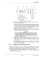
Remove the piston-cylinder module from its bullet case.
Select a piston-cylinder
module. Open the piston-cylinder module bullet case by rotating its lid counterclockwise.
Remove the piston-cylinder module from the bullet case base by unthreading it from the case.
Hold the piston-cylinder module body by the knurled area and rotate it counterclockwise.
Note
PC-7100/7600 piston cylinder modules are complete, integrated
assemblies that contain the piston, cylinder, mounting hardware, and
spring preloading system. There is no need to disassemble the module
for installation into the PG9602 mounting post.
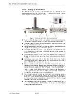
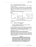
Place the piston-cylinder module in the PG9602 Platform mounting post.
Place
the piston-cylinder module (thread down) into the PG9602 Platform mounting post.
Screw the piston-cylinder
module into the PG9602
Platform mounting post.
Rotate the piston-cylinder
module clockwise until all
threads are engaged and there
is NO gap between the piston-
cylinder module and the top of
the PG9602 mounting post.
Slight resistance
will be
encountered in the second half
of travel as the piston-cylinder
module O-rings seat in the
mounting post.
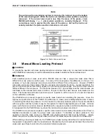
Figure 11.
Piston-Cylinder Module Installation
Caution
Low torque manual rotation is all that should be required to fully seat the
piston-cylinder module into the PG9602 mounting post. Never force the
piston-cylinder module into the mounting post.
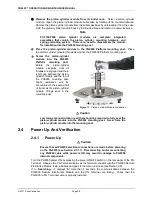
2.4
Power Up And Verification
2.4.1
Power Up
Caution
Ensure that all PG9000 electrical connections are made before powering
on the PG9000 (see Section 2.3.1.1). Disconnecting and/or reconnecting
any PG9000 cable while power is ON may result in damage to PG9000
internal components.
Turn the PG9000 power ON by pressing the power ON/OFF switch on the rear panel of the PG
Terminal. Observe the PG Terminal display as the terminal connects with the PG9000 Remote
Electronics Module, tests, initializes and goes to the main run screen (see Section 3.8).
If
<….Searching…..>
displays for more than 5 seconds, the communications between the
PG9000 Remote Electronics Module and the PG Terminal are failing. Check that the
PG9000 to PG Terminal cable is properly installed.
Summary of Contents for PG9000 Series
Page 10: ...PG9602 OPERATION AND MAINTENANCE MANUAL 2011 Fluke Calibration Page X Notes...
Page 128: ...PG9602 OPERATION AND MAINTENANCE MANUAL 2011 Fluke Calibration Page 118 Notes...
Page 164: ...PG9602 OPERATION AND MAINTENANCE MANUAL 2011 Fluke Calibration Page 154 Notes...
Page 188: ...PG9602 OPERATION AND MAINTENANCE MANUAL 2011 Fluke Calibration Page 178 Notes...
Page 192: ...PG9602 OPERATION AND MAINTENANCE MANUAL 2011 Fluke Calibration Page 182 Notes...


