


Page 65
© 2011 Fluke Calibration
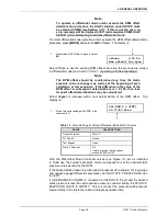
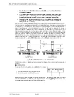
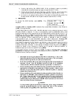
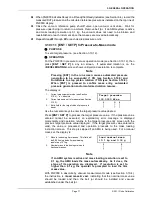
The second SYSTEM run screen displays:
1.
<n.nn°C>:
Current piston-cylinder
temperature. Source of value can be internal
measurement, normal or user depending on
current SETUP selection (see Section 3.11).
The unit of measure is degrees Centigrade
[°C]
and cannot be changed. Indicates
< ---- >
when information is unavailable or out of
range. PG9602 uses two internal PRTs to
measure the piston cylinder temperature when
internal temperature source is selected in
SETUP (see Section 3.11. The average of
these two PRT measurements is shown in this
screen. The individual PRT temperature
measurements can be viewed in the third
SYSTEM screen (see Section 3.10.5.3).
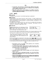
n.nn°C ±n.nn/min
nnn.n Pa ±nnn.n/min
2.
<+n.nn/min>:
Sign and numerical value of current rate of change of temperature. When
internal temperature source is selected for PG9000 the rate of change of temperature is based
on the average temperature of PG9602’s two internal PRTs. A negative value indicates
temperature decreasing. A positive value indicates temperature increasing. The unit of
measure is degrees Centigrade per minute
[°C/min]
and cannot be changed. Indicates
< ---- >
when information is unavailable or out of range. Indicates
< ---- >
when “user” or “normal” is
the current SETUP selection for piston-cylinder temperature source (see Section 3.11).
3.
<+nnn.n/min>:
Sign and numerical value of current rate of change of the vacuum reference
pressure, if present. A negative value indicates pressure decreasing. A positive value
indicates pressure increasing. The unit of measure is Pascal per minute
[Pa/min]
and cannot
be changed. Indicates
< ---- >
when information is unavailable or out of range. Indicates < -
TO - > if external device is not connected or communicating. Blank when in gauge or absolute
by ATM modes.
4.
<nnn.n Pa>:
Current vacuum reference value, if present (blank if not present). Can be normal
or other external measurement, normal or user depending on current SETUP selection.
Flashes when Not Ready and piston is floating (see Section 3.4.3). The unit of measure is
Pascal
[Pa]
and cannot be changed. Indicates
< >13 Pa >
if current SETUP selection is
COM2 and current measurement is out of range or greater than 13 Pascal. Indicates <- TO ->
if external device is not connected or communicating. Blank when in gauge or absolute by
ATM modes.
Pressing
[ESC]
in the second SYSTEM run screen returns operation to the MAIN
run screen. Pressing
[SYSTEM]
or
[
±
]
advances to the third SYSTEM run
screen. Pressing
[SYSTEM]
or
[
±
]
again, advances back to the first SYSTEM
run screen. All function keys are active from the second SYSTEM run screen
and operation returns to that screen when leaving functions that were accessed
from it.
Note
The current selection in SETUP determines the source of the
values used by PG9000 for piston-cylinder temperature and
vacuum reference values. If the SETUP setting is “user” or
“normal”, the SYSTEM screen displays the specified value, not
the real-time measurement from PG9000’s on-board sensors.
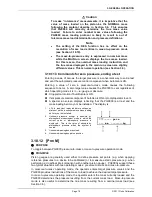
3.10.5.3 Third System Run Screen
OPERATION
The third SYSTEM run screen displays the individual temperature values
measured by the two internal PRTs. These are the source values for the
average temperature displayed on the second SYSTEM run screen.
To access the third SYSTEM run screen, press
[SYSTEM]
or
[
±
]
twice from the
first SYSTEM run screen, or once from the second SYSTEM run screen.
Summary of Contents for PG9000 Series
Page 10: ...PG9602 OPERATION AND MAINTENANCE MANUAL 2011 Fluke Calibration Page X Notes...
Page 128: ...PG9602 OPERATION AND MAINTENANCE MANUAL 2011 Fluke Calibration Page 118 Notes...
Page 164: ...PG9602 OPERATION AND MAINTENANCE MANUAL 2011 Fluke Calibration Page 154 Notes...
Page 188: ...PG9602 OPERATION AND MAINTENANCE MANUAL 2011 Fluke Calibration Page 178 Notes...
Page 192: ...PG9602 OPERATION AND MAINTENANCE MANUAL 2011 Fluke Calibration Page 182 Notes...


