

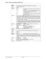


PG9602™ OPERATION AND MAINTENANCE MANUAL
© 2011 Fluke Calibration
Page
160
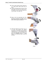
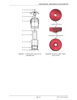
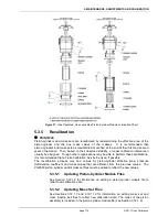
Loosen
-
but do not remove
- the four socket head screws (3 mm) located on
the PRT/cable pass through plate. The plate is located on the underside of the
platform. Make sure to note the location of PRT1 and PRT2: PRT1 has longer
leads than PRT2. PRT1 installs in the mounting post hole that is furthest from
the circular connector location on the rear panel. Maintaining orientation of
PRT1 and PRT2 assures consistency of piston-cylinder temperature
measurement.
The PRTs are able to be removed by gently grasping the shafts (not the
wires) and sliding out in a straight motion.
Slide the PRTs out of the mounting post.
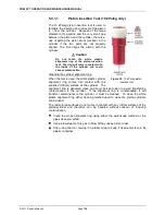
Note
Once the PRTs are removed from the Base it is recommended
that they be reconnected to the REM for temperature readout.
The REM includes 100 and 107 ohm reference resistors .
Reading resistance on the PRTs in combination with the REM
includes any errors contributed by the reference resistors and
the ohmic measurement circuit.
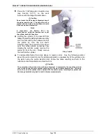
After reinstalling the PRTs in their correct position (see step 5) and tightening
the four socket head screws, reassemble in the reverse order. Thermal
grease may be applied lightly to the PRTs, if available.
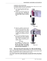
Reconnect the PG9000 terminal to the PG9000 Platform using the
cable supplied.
Power up PG9000 and verify proper operation of all on-board sensors.
5.2.1.6
Reference Vacuum Sensor (optional)
PURPOSE
To view and adjust the output of the reference vacuum sensor.
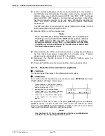
OPERATION
To view the output of the reference vacuum sensor, press
[SPECIAL]
and select
<7cal>, <6vac>
,
<1view>
. The display is:
1.
Current reading of the vacuum sensor in
Pascal. Reads
“> 13”
whenever the current
reading is greater than 13 Pa.
2.
Indication that this is a vacuum display.
3.
Current value of the Vacuum Multiplier
applied to the vacuum sensor reading.
4.
Current value of the Vacuum Adder (always
in Pa) applied to the vacuum sensor
reading.
6.52 Pa vac
VA 0.5 VM 0.99984
To adjust the values of VA and/or VM press
[SPECIAL]
and select
<6vac>
,
<2cal>
to access a screen in which the values of VA and VM can be edited.
From here, press
[ESC]
and select
<6vac>
,
<1view>
to view the vacuum sensor
reading with the edited calibration coefficients applied.
Note
See Section 5.2.1.1 for an explanation of Adders and Multipliers
and their use in adjusting internal sensors.
Summary of Contents for PG9000 Series
Page 10: ...PG9602 OPERATION AND MAINTENANCE MANUAL 2011 Fluke Calibration Page X Notes...
Page 128: ...PG9602 OPERATION AND MAINTENANCE MANUAL 2011 Fluke Calibration Page 118 Notes...
Page 164: ...PG9602 OPERATION AND MAINTENANCE MANUAL 2011 Fluke Calibration Page 154 Notes...
Page 188: ...PG9602 OPERATION AND MAINTENANCE MANUAL 2011 Fluke Calibration Page 178 Notes...
Page 192: ...PG9602 OPERATION AND MAINTENANCE MANUAL 2011 Fluke Calibration Page 182 Notes...


