


PG9602™ OPERATION AND MAINTENANCE MANUAL
© 2011 Fluke Calibration
Page
28
2.4.5
Verify Proper Operation of Ambient Conditions
Measurements
PG9000 automatically measures ambient conditions and uses these conditions in its
pressure calculations.
To verify that the ambient condition measurements are operating properly proceed as follows:
•
Display current ambient condition readings:
Press the
[AMBIENT]
key. The ambient
conditions run screen is displayed (see Section 3.10.6).
•
Verify proper ambient condition readings:
Compare the ambient condition values
displayed to the actual values of ambient conditions. Refer to the ambient condition
measurement specifications when evaluating the ambient readings (see Section 1.2.1.3).
Note
•
The unit of measure in which ambient pressure is displayed is the same as
the unit selected by pressing [UNIT] (see Section 3.10.3). Units of measure
in which other ambient condition values are expressed cannot be
changed.
•
PG9000 allows the source of ambient condition values used in reference
pressure calculations to be specified. The source may be PG9000’s on-
board measurements, a normal value or operator entered values. See
Section 3.11 for information on specifying the source of ambient
condition values used by PG9000 in reference pressure calculations.
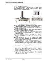
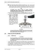
2.4.6
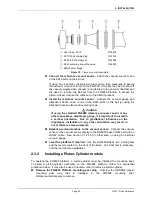
Apply Pressure To The Piston-Cylinder Module
Note
This section assumes the use of a manual mass set and that the PG9000
system assembly has been completed, including pressure interconnection
(see Section 2.3).
If an AMH mass set is being used, then the AMH-100 operation must first
be verified before proceeding. Jump to Section 2.4.10 for initializing and
verifying AMH operation.
Caution
Before applying pressure to the PG9000 system, be sure that all pressure
vessels and connections are rated for the pressure that will be applied and
that all connections have been properly tightened.
Continuing with the PG9000 verification process requires applying pressure to the piston-cylinder
module and floating the piston. Proceed as follows:
Turn OFF automated piston rotation and automated pressure generation (if
present).
This will prevent the automated rotation and pressure generation features from
interfering during verification of these features (see Sections 3.10.8 and 3.10.9 for
information on automated piston rotation and pressure generation).
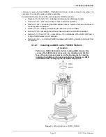
Load mass on the piston.
Install the mass loading bell on the piston if it’s not already
loaded. Then load the
make up
mass (4 or 9 kg) (see Section 2.3.1.3).
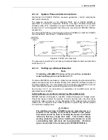
Float the piston.
Use the pressure generation/control component of the PG9000 system
to apply pressure under the piston through the PG9000 Platform TEST port. The piston
will float at a pressure approximately equal to the piston’s mass-to-pressure conversion
factor multiplied by the mass load in kg. The piston-cylinder conversion factor is marked
on the top of the piston cap and is in units of kPa per kilogram [kPa/kg].
Summary of Contents for PG9000 Series
Page 10: ...PG9602 OPERATION AND MAINTENANCE MANUAL 2011 Fluke Calibration Page X Notes...
Page 128: ...PG9602 OPERATION AND MAINTENANCE MANUAL 2011 Fluke Calibration Page 118 Notes...
Page 164: ...PG9602 OPERATION AND MAINTENANCE MANUAL 2011 Fluke Calibration Page 154 Notes...
Page 188: ...PG9602 OPERATION AND MAINTENANCE MANUAL 2011 Fluke Calibration Page 178 Notes...
Page 192: ...PG9602 OPERATION AND MAINTENANCE MANUAL 2011 Fluke Calibration Page 182 Notes...


